Miro for Design Engineers: Enhancing Solidworks Workflows and Prototyping
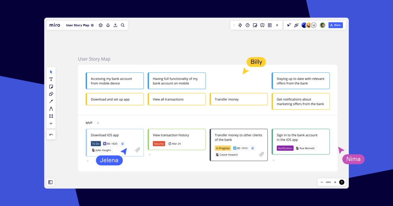
Realtime Collaborative Whiteboard Tools (like Miro) for Design Engineers Design engineers play a crucial role in creating innovative products and solutions, utilizing powerful software like Solidworks for 3D modeling and prototyping. However, the design process often requires effective collaboration, brainstorming, and visual communication with team members, stakeholders, and clients. This is where Miro, a versatile […]
Miro for Design Engineers: Enhancing Solidworks Workflows and Prototyping Read More »