This is a SOLIDWORKS CSWA exam guest article by SolidProfessor.

The Certified SOLIDWORKS Associate (CSWA) exam will test your skills in a variety of ways. The exam challenges your design knowledge, accuracy, and speed, so it’s a good idea to prepare ahead of time and be aware of the things you’re likely to encounter during the test.
There are several SOLIDWORKS features and mates that are commonly used in CSWA exam questions. Having prior knowledge of these features and mates will ensure you’re not caught off-guard during the test, so you won’t lose precious time. In this article, learn which SOLIDWORKS features and mates you need to know to confidently take the exam and earn your CSWA.
SOLIDWORKS Features Commonly Used on the CSWA
The CSWA covers many topics, including boss and cut features, fillets and chamfers, patterns, dimensions, and feature conditions. The CSWA can test you on any of these topics but not all will be covered in your exam. Here are the features you’re most likely to run into:
- Extruded boss
- Revolved boss
- Extruded cut
- Revolved cut
- Linear pattern
- Circular pattern
- Mirror
- Draft
- Fillets
- Chamfers
Before you take the exam, make sure you are comfortable with creating all of these features!
Learn how to create these features with the SOLIDWORKS Essentials for Part Design online course!
Quick review of SOLIDWORKS feature conditions
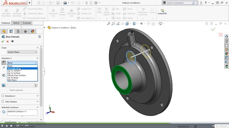
It’s also important to know feature conditions for the CSWA. When you create a feature in SOLIDWORKS, you have the option to change the feature’s start condition and end condition.

The start condition tells SOLIDWORKS where you want to begin the feature. More often than not, you’ll simply choose to start the feature from the sketch plane, but you also have the option to start the feature from a surface, face, plane, vertex, or offset.
Sidenote — if you’re using SOLIDWORKS 2016 or earlier and you select Surface Face/Plane, you have to make sure that the projection of the sketch is completely within the surface you select and that it’s only projected onto a single face. If it’s not, the start condition will not work.
Similarly, the end condition tells SOLIDWORKS how you want the feature to extend or end. Here’s what you can do with different end conditions:
- Blind: set a depth.
- Through All: make sure the feature extends from the sketch plane through all existing geometry in one or two directions.
- Up To Next or Up To Body: extend the feature up to the next surface or body.
- Up to Vertex or Up To Surface: specify a vertex or surface as the end of the feature.
- Offset From Surface: extend the feature to a specific distance from a selected surface.
- Mid Plane: extend the feature in both directions equally.
SOLIDWORKS Mates Commonly Used on the CSWA
The CSWA exam features a number of assembly creation questions. These questions will ask you to build an assembly using a variety of mates. SOLIDWORKS can test you on any of the standard mates. Chances are you’ll encounter most, if not all, of these mates so be sure to review them before your exam!
- Coincident: As the name implies, a coincident mate positions two faces, edges, or vertices together so that they touch.
- Parallel: This mate creates a parallel relationship between two components in SOLIDWORKS. This is helpful when you need to have two components that move in unison but aren’t necessarily in contact with each other.
- Perpendicular: This creates a perpendicular relationship between two faces. For example, when you want to constrain two entities so that they’re at a 90° angle.
- Tangent: This lets you add tangency relationships between two components when one of them has a curved face.
- Concentric: This lets you add a mate between two concentric features so that they share the same center axis. For example, you would use a concentric mate when you want to center a bolt in a hole.
- Distance: If you want to define a gap or distance between components, then you can use a distance mate to define that distance.
- Angle: Apply an angle mate to two components to control the angle between them. You can apply an angle mate between the axis of a cone and the axis of a cylinder, the face of a component and a line, two planes, and several other combinations.
If you want to learn more about SOLIDWORKS mates, watch these SOLIDWORKS Essentials for Assembly Design video tutorials!
Preparing for the CSWA exam takes a lot of practice and preparation, but earning your certification will open up new opportunities for your career. Here are some free resources to help you feel confident in taking the exam:
- [E-GUIDE] 30+ Expert Tips for Passing the CSWA Exam
- [CHEAT SHEET] SOLIDWORKS Keyboard Shortcuts
- [ARTICLE] Answers to the Top CSWA FAQs
Plus, check out SolidProfessor’s Certified SOLIDWORKS Associate Prep course to get familiar with the structure and style of the exam, walk through sample exercises from every aspect of the test, and practice for the multiple-choice section.
