
This one falls into my “answer the question, don’t worry about being pretty” rant perfectly. The secret to this one is that sketch entities cannot be reference UNLESS they are in the same drawing view.
Read the rant and find the rest of the solutions at the CSWP Drawing Overview.
The SolidWork’s official sample exam can be obtained here:http://www.solidworks.com/sw/support/29479_ENU_HTML.htm
Problem: Insert part into drawing that has an imbedded line segment.
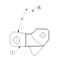
My solution: First I try to insert the part into the drawing. Ah- the part is not aligned to any coordinate system.
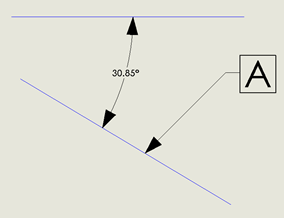
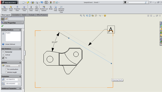
So my first step is to measure the angle of the line in the drawing. (Sketch a horizontal line, and then dimension). Watch out when you are dimensioning. The angle is adjustable.
Step #2- Open the part and measure the angle from the horizontal surface and the angled surface.
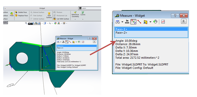 |
| Measure the angle using the measure tool – Make sure to select the right edges |
Step #3- put on your math cap and figure out the angle between the 2 lines. Should be 30.85-10=20.85. Done.
For those of you who are uncomfortable with my shenanigan shortcuts, here’s one “right” ways to do it.
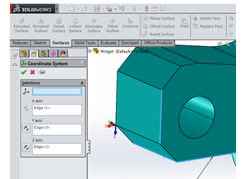 |
| Select an X-Acis, Y-Axis and Z-Axis to properly align the part |
First: go to Coordinate System in the part Select a X-axis, Y-axis and Z-axis that will align the part.
Drop the part into an assembly. Since it’s the only part- it automatically becomes “fixed”. Switch it to “Float” by right clicking on the part in the feature tree.
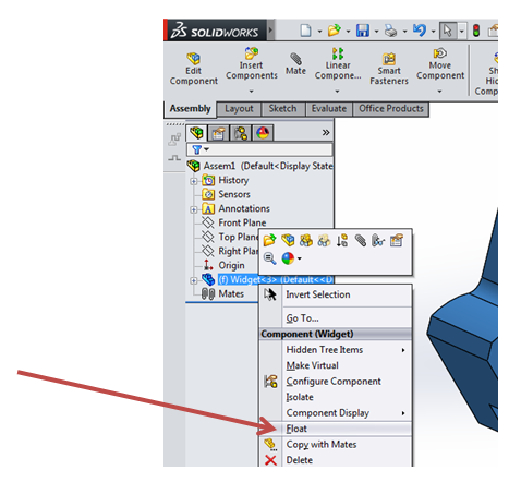 |
| Float should be available by right clicking the part in the feature tree |
Then mate the new coordinate system to the assembly origin. Now drop the new assembly into the drawing. Get the view you want. Last, copy the line in the drawing (line A) by hitting Ctrl C, Click in the drawing view and hit Ctrl V. You can now get a dimension between the additional parallel line and the part.
Deep down in my soul, I feel like there is probably an easier & cleaner way to do this, but I haven’t found it. Let me know if you know what it is. Thanks-

Jim is a CSWP and on the road to getting his CSWE. He works for HawkRidge Systems, an authorized reseller of SolidWorks. Jim also runs i-elf, a product development consulting company. He can be reached at Jim.Lucas@i-elf.com.
Their is an easier way of doing this. in the drawing go to INSERT>RELATIVE TO MODEL. From there open your model and select the planes you want to use to create and orgin point.
Move/Copy Bodies. You just align the part with the reference planes and that is it.
There is another way:
go to Coordinate System in the part Select a X-axis, Y-axis and Z-axis that will align the part.
Save a part like a step file, but before saving, on the saving windows choose options and there you need to choose coordinate system that you have created before. Save a part. Insert that new part (step file) into the drawing and you could measure an angle 🙂
I was taught another way to do this:
1) Open the part and select the face that is parallel to the page as shown in the sample image.
2) Rotate the view normal to this face (CTRL + 8).
3) Create a sketch on any face that has a vertical line and a line collinear with one of the edges that /should/ be vertical.
4) Remove the vertical relation from the vertical line. (Be sure not to change the angle of the line)
5) Dimension between the two lines, copying the value. (We removed the vertical relation to allow this value to be driving, and therefore easier to select and copy)
6) Go to Settings > View > View Rotation and paste the value that was copied into the “Arrow keys:” field.
7) Using the alt and arrow keys, rotate the part once so that it aligns with the view in the image. (I always forget if I’m supposed to use the right or left arrow key, so I just try one and if it doesn’t work, use the other)
8) Save this as a named view.
9) Don’t forget to change the “Arrow keys:” field back to 15.000 deg, or whatever value you had before changing it.
The named view can be inserted into the drawing, and the line can be copied and pasted into the view (copy the line, then activate or lock the view, then paste). I don’t know if this is “an easier & cleaner way to do this”, but it is at least another method for anybody studying for the exam. Hope it helped!
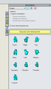
Inserting a relative view (found on the View Layout tab) using two faces on the part seems to be the actual “easier & cleaner way”. Much simpler!