
After reviewing the basic steps of parting lines it’s easy to realize that not every part is so cut and dry. Sure for the sample CSWP mold tools exam the parts are easy to understand and surfaces are easy to define but what about on the real test? Or the real world? When looking at creating shut-off surfaces the knowledge of true mold design will begin to come into play. Where is it best to have mold halves meet, at what angle should they meet, how will a tool room machine the result, and how will the part and molding cycle be effected. And what is shut-off anyway? Where two halves of a mold meet, and thus the flow of material is “shut-off” is a shut off surface. In solidworks this generally refers to the interior portions of a part as much of the shut-off will actually be define by the parting line surface (though the parting line surface would still be referred to as a shut-off surface/face to a tool maker). For a mold insert knowing what is shut-off and therefore requires tight tolerance, to ensure no material leaks through he gaps, can be critical and sometimes these will be highlighted or called out on prints differently.
For the purposes of the CSWP mold exam and shut-off creation my first review will be simply on the options allowed by the tool. Other concerns, such as those questions stated above I’ll go over as part of the mold design review. Neither will be comprehensive but both should garner some insight as to what things should be considered.
First up, the sample exam. Question two on the sample exam asks for the surface area of the shut-off surfaces. Hopefully the real exam is a bit more involved as this can actually be answered geometrically (pi*r^2 of the circle minus measured surface area of top face). But of course using the proper way will eliminate any questions and because the answer is to 4decimal places it is actually necessary.
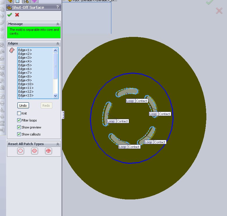
Open the part and allow the software to import geometry if it can. Then click the “shut-off surfaces button”. Now Solidworks does it’s magic and looks at the part to see if it can pick out what holes this shut-off will fill. The puck shown below has all surfaces recognized immediately.
So then how to measure the surface area of a face. Again built in tools, this time the measure tool, will take care of that (Tools-Measure or hopefully a toolbar or S-Key)
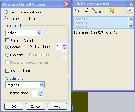
If the settings are such that the value is not carried to the correct number of digits the button can be clicked to bring up a “Measure units/Precision” window. For most of the exams I find it preferable to set my global settings to read at least 4 decimal places to save the few seconds of doing this on multiple questions.
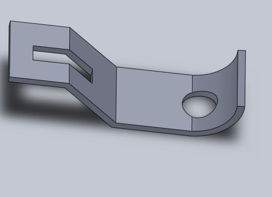
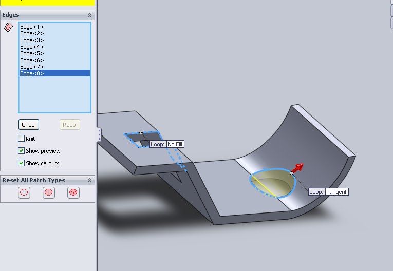
This all seems so easy though and doesn’t give a good grasp on what the shutoff surfaces tool can and should do. What if the hole that is being patched is not on a single plane? Here is a part that has some holes which would require non flat shutoff faces.
Now the software will not recognize them as easily so the edges of each hole must be selected manually. Once selected the display view will have a small call out noting what type of fill feature is being used to patch the surface. These are also in the feature manager section titled Shut off patch types. Another one of those “click and to see what it does” features.Clicking this will cycle through the options (No fill, Contact, All Tangent). All tangent typically is the one to go with if the surrounding surfaces are flat as this will create some nice flat faces which can easily be machined.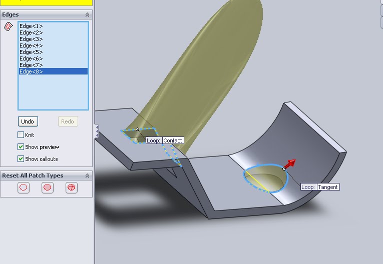 If for any reason the default options do not work surfaces can always be created manually. First run the shut-off surfaces feature and select the options but choose “No- Fill”. This will create the folders required in the feature manager but leave no surfaces.
Using other options from the surfaces menu (yeah, yeah, I’m getting to that test at some point) the holes can be manually patched. Knit the result to get a single surface that functions as a shutoff face. Then create a second IDENTICAL face using the offset surface feature (select 0.0 as distance to offset). 
Any surfaces that are manually created will naturally show up in the “Surface Bodies” folder of the feature manager (seen above). These surfaces then can be put into the “Cavity Surface Bodies” and “Core Surface Bodies” sub folders by drag and drop. Above I have already dragged one of them Surface-Knit1 into place.
Of course the details to surface bodies can be more complicated but all of this should provide a good foundation for the exam. It may however be worthwhile to look at a few of the surfacing tools to be certain if things must be done manually that you can still get the correct answer.
More review for the CSWP Mold Tools exam.
More on all of the CSWP Exams and preparation.