
Group End treatments or Single Corner
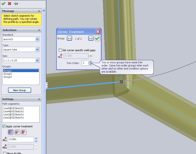 When adding weldment parts to a file the first step is grouping the components together. There are a variety of different ways to group but the important part to remember is that a group can only create intersections between two components. If a corner will have 3 or more weldments meeting at a point it will need to be controlled over two groups. In the image above the corner treatments on the group scale can be seen in the left feature manager pane. Highlighting the each group in the list will allow each to be edited separately. However, if a corner is more complex or needs a hands on approach it can be edited directly. Simply click on the pink dot at the corner vertex to bring up a selection window. In the above image it is seen on the right. The selections here will override any in the group.
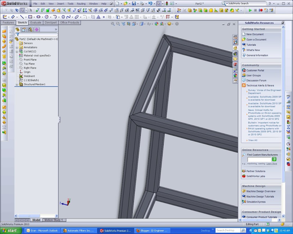
 Butt joints are the other main type. There are two options given in the main feature manager but really they just change the orientation.
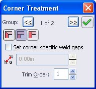
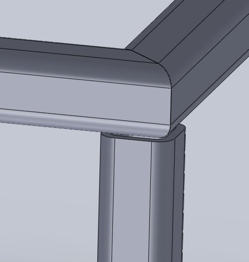
To solve this problem we want BOTH group 1 and group 2 to be looked at when solving the miter. In the single corner treatment box you can look at both groups (the arrows around the 1 of 2 in the above image will toggle). Instead of solving them in order change the trim order of both groups to be the same. Now the system will look at all three components when making the corner. This is how you can get the three spears meeting type corner seen in the first image
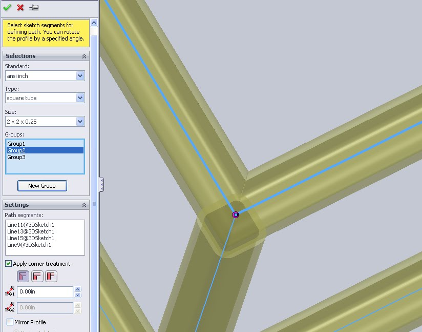
 Depending how the cuts to the extrusion will be made a simple corner may be all that is available. These are simple straight line cuts.
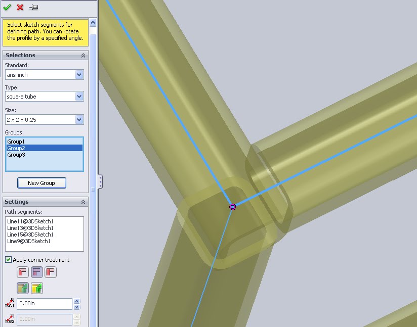
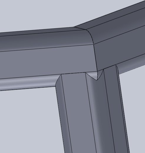 In contrast to the simple cut, the Coped cut creates a more detailed part. With some high end laser cutters it is possible to treat the edge of each length so that there is almost no gap. This can reduce the width of a required weld and greatly increase the strength of such parts. In modeling it also looks a lot nicer as all edges will be complete and the areas of white space or background that would have been filled by welding wire anyways will be sealed. When making a cut list and drawings though these edges can become a nightmare. Again, unless a sophisticated CNC machine is going to use this data directly the headache of odd lengths etc should be avoided.
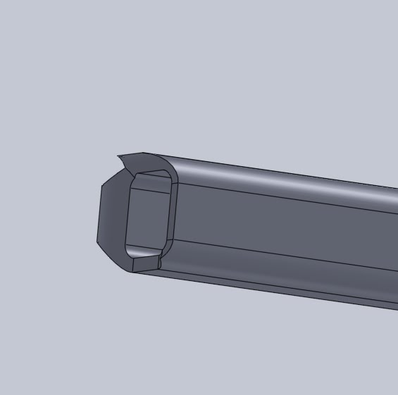
On the exam I am sure it will be important to identify a few corners and knowing what each feature does will surely help. For more review on the CSWP Weldment exam check the main post.
thanks, got the answer I was looking for.
Pingback: CSWP: Weldments – 3D Engineer