
End caps for weldments are rather basic. This is one of the areas where the software knows what typical design intent is going to be, and a feature specific to that task has been created. Not having worked directly in an industry where weldments are regularly used I have no idea whether or not this is an accurate representation of the manufacturing process. Other functionality in Solidworks does this (I’m looking at you mold tools) where although it is a nice idea, most engineers or designers have an alternate way that more closely resembles their fabrication process.
Still though, this is likely to be on a weldment exam as they love making sure you can tweak the settings of these rather basic tools. So let’s see what can be done.
To start an end cap simply click the End cap icon. ![]()
![]() A feature manager will appear asking for a face selection. Choose the end face of the component to cap.
A feature manager will appear asking for a face selection. Choose the end face of the component to cap.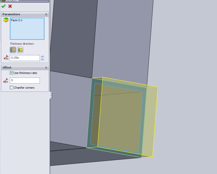
Play around with the depth value and thickness ration values to see what each does. Below I noticed that setting an offset value that is greater than the part thickness causes a failure as should be expected.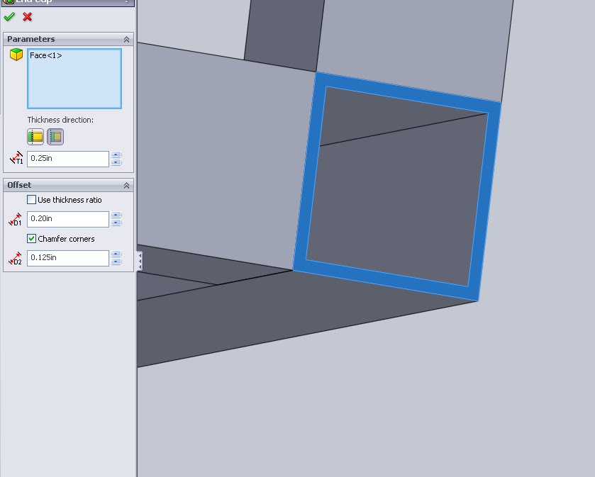
The offset value is measured from the outside of the part. A ratio can also be used by clicking the check box.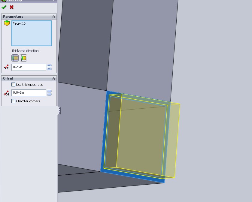
Cap direction: Above the outside end cap is shown as it extends beyond the edge of the part. Below an inside end cap was created. This keeps total component from extending out where someone can smack their shin and instead cuts off an equivalent depth from the end of the main component. If for any reason the face at the edge of the weldment is used for any other mating entities this function can create errors.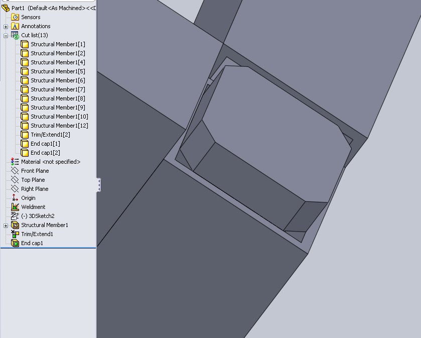
Chamfering the cap is also an option and is definitely a candidate for being on the test. Visually a chamfer is easy to recognize and the value of it should be clearly noted on any print or attached model. Simply type in the value and the chamfer is added.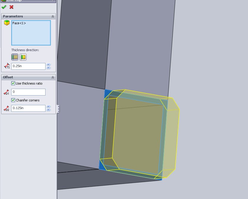
The end cap feature also changes the cut list. Because the cap is an actual piece it creates another cut entirely. In addition, the segment that is capped will be renamed to reflect that it is capped.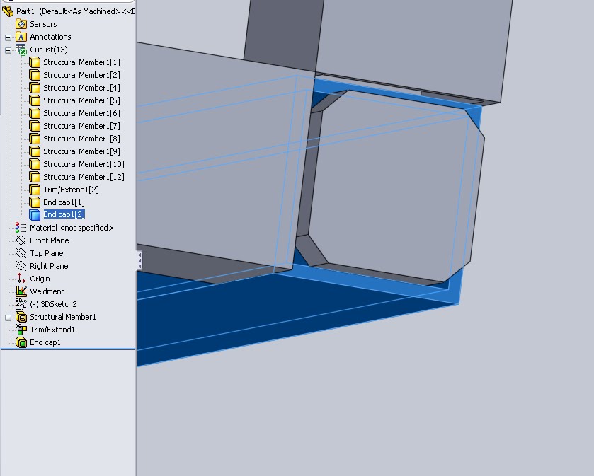
If multiple End caps are created they will be noted in the cut list with their corresponding numbers. Below I have 2 end cap features that create a total of 3 end caps. The first end cap is denoted as End cap1[1]. The 2nd and 3rd end caps are on a single section meaning only 3 components are a part of End cap2.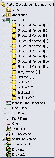
The naming scheme of these also caught my eye. The cut list will dynamically update to the name of the feature in the tree. To be certain of this I tested it out by only renaming the feature and this was the result.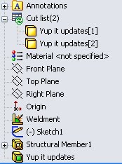
If by chance a member needs to be capped on both ends, but with caps of varying values, the member itself will not be name for both of them. Rather the history of the tree will take over and the component will be name for the last feature that acted upon it. Basically this is to say that not every end cap necessarily requires 2 corresponding members. This all may sound a bit verbose but with the need for an accurate weldment cut list (it’s part of the required knowledge for the CSWP weldment exam) I found it important to note.