
Preparing for SOLIDWORKS certification? Get CSWP prep tutorials and practice exams from SolidProfessor, and see our full SOLIDWORKS Certification Guide.
One of the most common ways to lose points on the CSWP exam is modeling a part around the wrong origin. Many exam questions ask for the center of mass, and those coordinates are measured from a specific origin shown on the drawing. If your part is built from a different point, the mass will be right but the center of mass will be wrong. The good news is that you don’t have to remodel the part. This tutorial shows how to fix it in about 30 seconds with a coordinate system.
Why the Origin Matters on the CSWP
Mass and volume don’t depend on where the origin is, so an early question that only asks for mass won’t reveal the mistake. The problem shows up when a later question asks for the center of mass relative to the origin in the drawing. If your part origin sits somewhere else, every coordinate will be off, even though the geometry is perfect.
Start by making the origin visible so you can check it. If it isn’t already showing, turn on origins with View > Hide/Show > Origins. Compare where your origin sits to the origin marked on the exam drawing before you move on.
Scenario: You Modeled From the Wrong Origin
Say you build the part for question 1 and report its mass. That answer doesn’t depend on the origin, so it’s fine. Then question 2 asks for the center of mass, and you realize the part was modeled from the wrong corner. It took 20 minutes to build, and remodeling it would eat up time you need for the rest of the exam. Instead, add a coordinate system at the correct location.
How to Fix It With a Coordinate System
1. Insert a coordinate system at the correct origin
Go to Insert > Reference Geometry > Coordinate System (or use the Reference Geometry drop-down on the Features tab). In the PropertyManager, select a vertex or point for the new origin, then select edges or axes to define the X, Y, and Z directions so they match the drawing.
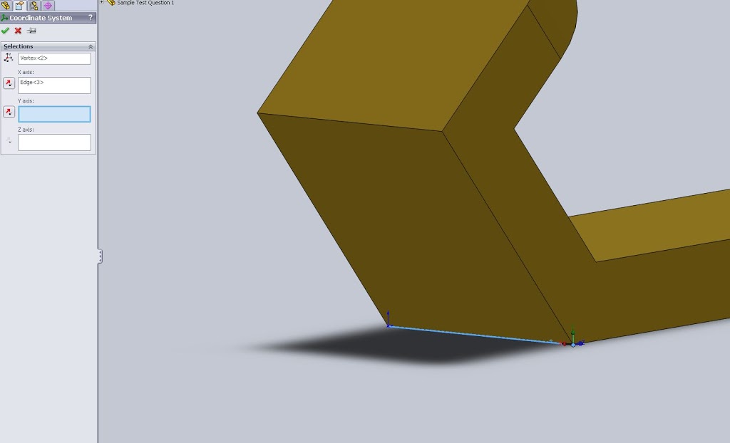
2. Open Mass Properties
Click Mass Properties on the Evaluate tab, or go to Tools > Evaluate > Mass Properties.
3. Report values relative to the new coordinate system
Near the top of the Mass Properties window, find the drop-down that sets which coordinate system values are reported relative to. Change it from the default to your new coordinate system and the center of mass values update immediately. Below you can see the results from the default coordinate system at the part origin, followed by the corrected coordinate system.


Placing a new coordinate system takes about 30 seconds and saves plenty of time for the rest of the test. The same approach works for moments of inertia and for any other value the exam asks you to report from a specific point.
Tips to Avoid Origin Mistakes on the CSWP
- Read the drawing first. Before sketching anything, find the origin and axis directions shown on the exam drawing.
- Start your first sketch at the origin. Sketch the base feature on the plane and location the drawing specifies, so later features inherit the right reference.
- Check units and material. A correct origin won’t help if the unit system or material is wrong, so confirm both before reporting any mass property.
- Keep your coordinate system. If later questions modify the same part, the coordinate system stays in the feature tree and keeps reporting correct values.
More CSWP Study Resources
- How to Pass the CSWP: 11 Tips from Engineers Who Did
- CSWP Prep: Setting Up Files and Equations
- What to Expect on the CSWP Exam
- SOLIDWORKS Certification Guide: CSWA, CSWP, and CSWE
Get more SOLIDWORKS help for certification with online CSWP training from SolidProfessor. 3DEngr.com readers get 25% off a personal SolidProfessor membership with promo code 3DENGR25.
Cool Chris. Thanks!
Very helpful mate !
Thanks !
Thank You!! Big Help!
Is it possible also to use this method as a means of stating origins for parts in assembly systems.
This tutorial is the closest to origin alteration I have found with out remodelling.
Question i have if any one knows can one reset origins of parts when updating assemblies. )i.e same part but change the origins to update in the assembly file. like here with this coodinat tool but inassembly fle not a part file.
Thank you very much for this post it has been a tremendous help
how can you move the origin i don`t nmeed the center of mass mainly i need to chnge the origin because in when i import in other cam program it puts the axis on the origin….