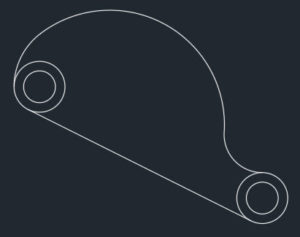
Parametric drawing is a method of making geometries with the help of constraints or restrictions. AutoCAD introduced this feature back in 2010 and even after so many years of release the tool is still largely unknown or overlooked.
In this article, I have explained methods of using this feature with the help of a sample drawing. Let’s start by familiarizing with this tool.
Parametric Tab:
All the tools related to this feature can be found on the parametric tab. The first panel of parametric tab is dedicated to Geometric constraints like horizontal, vertical, concentric and tangent. The second panel is for dimension related constraints like linear, aligned and radial dimensions.

Let’s take the example of the drawing shown below. This drawing has no defined center point for most of the arcs and to make this geometry parametric tools can be most efficiently used.

In this case, we will start this drawing by making the concentric circles of radius 5 and 8 at two different points. You can also make the line connecting the two concentric circles tangentially using the tangent option of object snap.
The final drawing after making these geometries will look like this.

The remaining part of the drawing can be made with the help of geometric and dimensional constraints of parametric tools.
Using Constraints:
To make the first arc on top of the top left circle select the three-point arc option and make an arc clicking at three random points in the drawing approximately taking the shape of an arc in the drawing. You don’t need to be specifically concerned about connecting the arcs tangentially or making them of any specific radius. Make the second and third arcs as well in a similar way with three-point arc tool. The final geometry should look similar to this one.

Now go to the Geometric panel and click on the Fix icon which looks like a Lock. Click on the circle of radius 8 units on the top left of geometry and then repeat the process for the circle on the bottom right circle having a radius of 8 units. You will notice that a lock icon will be placed close to both of the circles and their centers will have a red X sign indicating that their position is now locked.
Select Radius icon from the dimensional panel and click on circles on which Fix constraint are applied. You will notice that Rad1 and Rad2 constraints each of 8 units will be applied to both of the circles essentially restricting its radius from any change.
Apply the radius constraints to all of the arcs made in the drawing and change the value of radius to their respective values in the dimensional constraints as shown in the image below.

Once again move to the Geometric panel and select tangent constraint. Click on the circle of radius 8 units on the top left side of the geometry and then click near the left end of the arc of radius 21 units. You will notice that the arc will become tangential with the selected circle. Repeat the process with the arc of radius 12 units and circle of radius 8 units on lower right corner. Finally, apply tangent constraint between the arc of radius 36 and radius 21 and 12 units. The final geometry after applying these tangent constraints should look like this image shown below.

If you select any of the arcs and move them in the drawing area it will move in 2D space with all the constraints. In order to make drawing fully constraint select the arc of radius 12 units and move its center on the vertical line passing through the center of concentric circles on the lower left side of drawing area then apply fix constraint to the center of the arc. Similarly, move the center of the arc with radius 21 units on the horizontal line passing through the center of concentric circles on the top left of the drawing and apply fix constraint on the center of the arc.
Now the drawing is fully constraint and we can trim/extend extra geometries to clean up the arcs. The final drawing will look like this.

In this drawing, you will notice that there are many geometric as well as dimensional constraints that make drawing cluttered. In order to remove the constraints select Delete constraints option from Manage panel of the Parametric tab and select complete geometry and press enter.
The completed drawing will look like image 2 shown in the beginning of the article.
Applying Automatic constraints:
You can quickly apply automatic geometric constraints on any drawing. For applying the geometric constraints select the Auto Constrain option from the Geometric panel of Parametric tab then select complete drawing and press enter. The drawing will not become fully constraint as many dimensional constraints and also some geometric constraints will not be applied automatically and you have to manually add those constraints.
You can also keep infer constraints option ON to apply geometric constraints automatically to geometries on the go. To activate infer constraints select its icon from status bar or change the value of CONSTRAINTINFER system variable to 1.
![]()
When the Infer Constraint option is active the geometric constraints will be applied automatically to the drawing while creating it. In this case, also you can remove constraints by Delete Constraints option of Manage panel.
Do you also use these parametric tools in your drawings? Let us know in the comments below.
 About the Author:
Jaiprakash Pandey is a Mechanical Engineer currently working as CAD Corporate trainer. He is an Autodesk AutoCAD certified professional and an Autodesk expert elite member. He provides training in AutoCAD, CATIA and other CAD products to corporate clients. He is a regular contributor to AUGI world magazine and he also develops AutoCAD video courses for Pluralsight and his own platform SourceCAD. You can reach his blog SourceCAD for more AutoCAD tips.
