This is a guest article from SolidProfessor on design for additive manufacturing: Factors to consider and pitfalls to avoid.
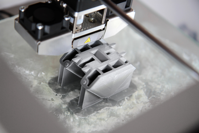
Additive manufacturing can be defined as any process where materials are added together to form a finished product. This definition can apply to a wide range of processes, but in the engineering design world today all the buzz is around 3D printing. 3D printing was originally used as a faster way to build prototypes. And while this is still true, technologies such as multi-jet fusion (MJF) printers are rapidly transforming 3D printing into a scalable method for high-volume manufacturing.
With traditional manufacturing methods, such as injection molding or casting, designers must be aware of constraints including draft angles and overhangs so designs can be released from a mold. These constraints usually mean that components must be manufactured separately and then assembled. But when it comes to designing for additive manufacturing (DFAM), engineers have a lot more freedom and flexibility. Theoretically, it’s possible to 3D print just about anything since it’s a layer-by-layer process.
DFAM makes it easier to let your imagination run wild, but it still comes with its own rules to follow to ensure manufacturability, desired aesthetics, and mechanical properties. In this article, we’ll examine several factors to consider and pitfalls to avoid when designing for additive manufacturing.
WATCH NOW: Online Tutorials for Design for Additive Manufacturing
Additive manufacturing can’t defy gravity.
3D printing is a truly amazing process, but it isn’t magic. You’ll need to include supports in your design in areas where a part has an undercut or outward sloping wall of 45 degrees or more and is normal/perpendicular to the part’s build orientation. Depending on the material you’re using in your design, you’ll be able to choose from up to three different types of supports: soluble, breakaway, and powder & machined.
Your build orientation matters in DFAM.
Topology refers to the way in which parts are interrelated or arranged. For DFAM topology, you specifically need to think about your build orientation (i.e., z-axis). If you consider your z-axis in the design process, this will help you minimize production time, maximize functionality and strength, and show the quality of your part before it gets into a built unit.
Understand the technology you’re designing for.
Additive manufacturing is more flexible than traditional manufacturing methods, but with this comes more complexity. In traditional manufacturing, constraints only vary slightly depending on materials. But with additive manufacturing technology, the constraints and considerations can be completely different from modality to modality. You’ll need to be knowledgeable about those differences. Here’s just a shortlist of the different technologies you could work with in DFAM:
- Fused Deposition Modeling (FDM)
- Vat Photopolymerization (SLA & DLP)
- Material Jetting
- Binder Jetting
- Sheet Lamination
- Direct Energy Deposition
- Powder Bed Fusion (SLS & MJF)
FREE ON-DEMAND WEBINAR: Access the free webinar recording “Demystifying Additive Manufacturing” from SolidProfessor, SOLIDWORKS, HP, and FORECAST 3D.
Consider finishing before you start.
Different additive manufacturing technologies will have different finishing options and constraints. While the vast majority of 3D printing process materials can be easily sanded or post-processed with most conventional coatings or paint, some technologies have more unique finishing options. For instance, FDM allows you to use a vapor finishing, and MJF lets you use dye. Consider these options before you begin your design so you can achieve your desired aesthetic.
Don’t just design for the part ‒ design for the build.
Designers working with traditional methods are used to manufacturing parts piece by piece until they have a full assembly. With 3D printing, not only can you produce complete parts, but you can also print multiple complete parts at one time. Whether you’re designing for an FDM, SLS, or an MJF printer, you’ll likely have about a cubic foot of build volume. If you’re intending to produce a relatively high volume of products, maximize your print cycles by fitting as many parts as possible in the build platform or 3D bed of powder.
BECOME A 3D PRINTING EXPERT: Go from simple prototypes to complex figures with online learning paths.
Don’t forget to think outside the box!
This is one of the most common pitfalls in DFAM. After decades of designing parts for traditional manufacturing methods, old habits can be hard to break. In fact, it’s fairly common for companies that offer industrial 3D printing services to receive parts that were originally designed for injection molding. You can use additive manufacturing to produce designs that were intended for traditional methods, but this leaves a lot of opportunity on the table for more innovation.
Additive manufacturing allows you to create more unique and complex designs while saving on manufacturing time, lowering costs, and improving functionality. Since DFAM offers so many unique benefits, make sure to take advantage of them.
SIGN UP: Accelerate your DFAM skills with SolidProfessor’s online, video-based training.