
B-2. Sketching
Sketching is the primary function and basis of nearly all Solidworks files. When creating a model from side views it is also one of the most intuitive ways to begin a model. Best practices for where to begin sketching (Top Plane, Right side view etc) will vary from modeler to modeler and company to company but a good rule of thumb is to start with the largest sketch with an eye for the most static elements (those that will not change). How to define and dimension a sketch is also important.
Solidworks is good at having features automatically snap to relations. Horizontal and vertical lines, edges and points snap to coincident. This can be both misleading and wrong given the inaccuracy of the pictures in the CSWP. Sides that look to be co-planar in the exam question figure may be just that, but they may change in future questions. Having a grid available helps lay things out with proper relations while still making sure the realtions do not overdefine or improperly define certain edges. Remember that for most CSWP questions the placement of the origin is critical in determining the center of mass so locating the part correctly about the origin in sketches also becomes a critical concern.
To turn on the grid check the box at(Tools>Options>Document Properties>>Grid/Snap> Display Grid)
To enable snap to grid check the box at (Tools>Options>System options>Sketch Relations/Snaps> Grid).
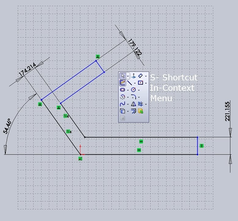
S key and RMB in-context menus: The single biggest time saver in newer version of Solidworks is the addition of in context menus. The RMB (right mouse button) brings up an in context menu that can be customized from a limited list. This is very helpful in flying through a quick sketch and eliminates the need to get the mouse back up to the tool bars. Even more powerful is the S key which brings up a shortcut menu of actions typically used in the current state and it can be customized with anything. Not only can the S key access all the sketch features needed it can also be customized to add such items as Extrude and Cut, the two most commonly used features following the sketch tool. Although the movement of the mouse to the top of the screen might seem like a small thing to eliminate over time this lightning quick access to any needed feature can significantly reduce the time spent looking for items. Setting up hot keys is useful not only for the CSWP exam but is a good practice in everyday use
Fully define all sketches. Making sure a sketch is fully defined is simply good practice. Under defined sketches cause major problems when changes must be made, arcs over extend, lines cross, dimensions loose defining edges, and features fail. It is much easier to go back and remove definition that it is to painstakingly correct each error caused by an under defined sketch. For visual purposes a fully defined sketch or sketch entity will appear black while under defined entities will appear blue. Once a sketch is complete click the RMB and get the in context menu. This will include an option for “Fully define sketch”. A property manager appears and allows the user to select the entities and relations to be defined. Sketches are known to be fully defined when they appear in the feature manager without a (-) in the sketch name. When updating values to manage multiple questions for the CSWP exam having a sketch fully defined will eliminate the need to trouble shoot problems and save a lot of time.
Don’t forget mouse gestures!