
The fold and unfold commands are unique from the flatten command in that they are time dependent. The Flatten feature appears at the end of the tree and can be suppressed and unsuppressed to view the flat pattern, but the fold and unfold features can appear anywhere in the tree. As with other Solidworks features that means that the software reads them in the order they appear in the feature tree.
It is sometimes the case that a feature must be punched over a bend. During the manufacture process these punches and cuts are created while the part is in the flat state, thus when designing them it is important to locate and model the feature while the part is flat.
1. Insert an Unfold feature and select the bend that the feature extends across.
2. Create the required geometry (typically a cut or hole)
3. Insert a Fold feature and continue modeling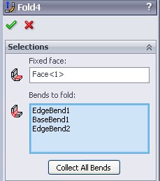
“Collect All Bends”
For the Unfold feature “Collect All Bends” will select every bend in the part, essentially mimicing the flatten feature. In Solidworks 2010 Sheetmetal parts can contain multiple bodies. When this is the case “Collect All Bends” will only select bends on the body connected to the “Fixed Face”.
When unfolding the “Collect All Bends” button will find and select all bends that are currently “Unfolded”, even if they were unfolded using multiple unfold features, assuming they are still on the same body.
When folding and unfolding selecting a “Fixed face” is important. If the “Fixed Face” of the Fold is different from the “Fixed Face” of the unfold part orientation will be thrown off. This could effect the part orientation in Assemblies depending upon the mating features.