
The parting line of a molded component is the intersection of the part and 2 mold components. Typically this refers to the line where the two sides of the mold meet. On many parts this feature can be visible to the naked eye but in good part design attempts are made to hide the line as much as possible. This can be done by locating the parting line in an unseen portion of the part, or by locating it in a position that blends the line with other part features (ie. mid plane axis, steps, edges, corners, etc).
The first step in defining a parting line is choosing the direction of pull. This is done by selecting a face that is perpendicular to the direction of pull. For the sample part any one of the flat faces works. Then run the draft analysis.
Check boxes do a few tasks to help ease modeling. Use for Core/Cavity basically just adds a few folders to the feature manager that are associated with the two (one folder for Core surfaces, one for Cavity surfaces). Split Faces is a little more helpful as it goes ahead and creates a split line on straddle faces (more on straddle faces and draft analysis). Since it was required to use this for the sample part I am assuming that most or all parts supplied for the exam will require this item to be checked.
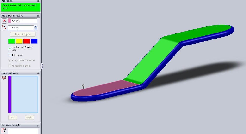
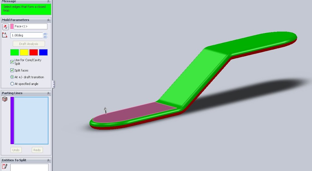
In these images you can see the red straddle faces (in blue) without the Split Faces box checked. Once checked this faces obviously no longer appear as blue.
An interesting note here, when doing the sample test I did have a few issues with these faces. If I selected the pull direction as +Y my draft analysis, question 2, resulted in negative draft faces count of 15 with 2 straddle faces. Flipping my pull direction in my parting line feature somehow eliminated this issue and gave me a nice 17 positive/17negative faces. Not sure yet if this is actually a part of the test as there is an outside chance it is part of the “imported part repair” they mention but I think this is an error. I say this here because I was about to note that checking the split faces box negates the ability to have straddle faces, but I guess that is not the case.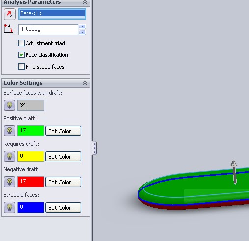
Above is the correct part, where the parting line feature has a direction of pull in the -Y direction.
Below is the result of the draft analysis where all that I have changed is the direction of pull of the parting line feature. This time in the +Y direction.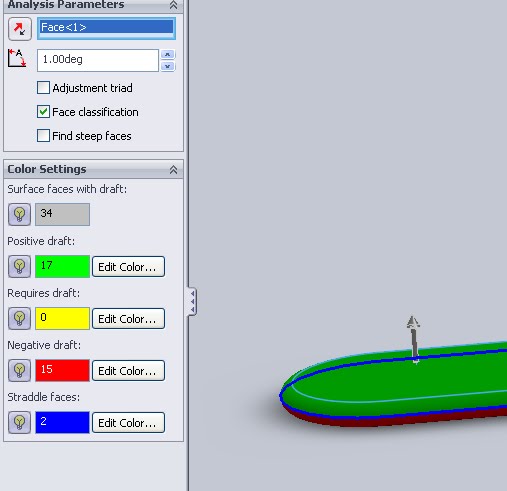
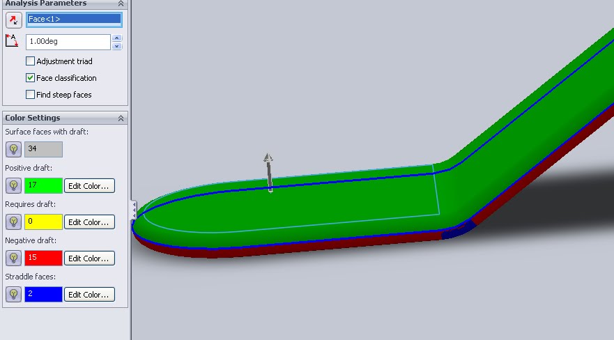 This last image shows which faces are “straddle” faces even after the split line box was checked. This seems especially odd as the parting line in both cases is identical.
Back to parting line creation, once the draft analysis is run and split faces selected all that is needed is the selection of one segment of the parting line. Find a intersection of a green (positive draft) face and a red (negative draft) face and you’ve got it. Use the auto select feature and the software will find a loop that satisfy a parting line.
More review for the CSWP Mold Tools exam.
More on all of the CSWP Exams and preparation.