
One of the best and worst parts about sheet metal design is that it is limiting. Just because something can be designed on a computer screen does not mean that it can actually be made, at least not economically. However, the up side to this is that once you know what can be done, so long as you stay within those parameters, it becomes increasingly easy to design a working part.
The most obvious application of this is in material selection. If there are only a few stock sheets to choose from to design then most of your default values will not have to change. Solidworks knows this and allows for a one time setup to save time, just like it does in other parts of the system (design library, toolbox). 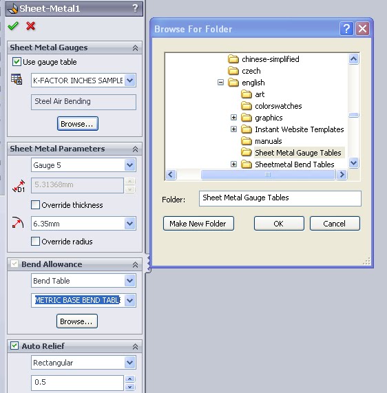 Once selected in the “Sheet Metal” feature all values will automatically be imported. The table used can be changed even after a part is fully modeled (although doing so will likely cause rebuild errors). To change this you can access the table in the “Sheet Metal” . To further consolidate information it’s even possible to create a Gauge-Bend table that links all of these values. When using a Gauge-Bend table an additional selection will be available under the Bend Allowance.
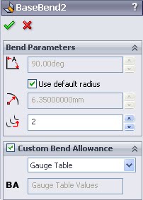
Above is the feature manager for a single BEND, where the bend allowance can be modified (see here again the option of Gauge Table is present because this part has an active Guage-Bend table). There can be many of bends defined within a single Flange feature, which means even if more than one Bend Allowance value is used it is still possible to have a neat tidy feature tree. In general (and in this case) a smaller feature tree results in a more efficient design in terms of rebuild time.
So now the big questions.
How do I setup or change a Gauge or Gauge-Bend Table in Solidworks?
Solidworks comes with a few basic tables that are stored in folder as part of the install (fittingly called “Sheet Metal Gauge Tables”). Take a look at the Sample Steel table and it is pretty easy to figure out how to add values. This is all done in Microsoft excel and most cells contain notes. Using the samples as a template it’s easy to do a quick “Save As” to get a new copy, then just change the values needed. Note that below I have excel open on top of Solidworks for viewing purposes you can also edit the table directly in Solidworks using Edit>Bend Tables>.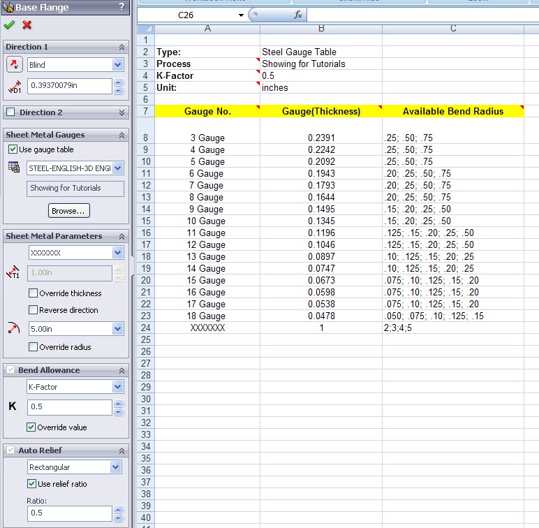
Check out the Sample “Bend Allowance” files to a joint gauge-bend table. Another note here, make sure the units selected in the table correspond with those in the part file. Although it’s possible to circumvent this it is much easier to recognize and alter items that are causing issues. Personally I spent about 30 minutes trying to figure out how to setup the fields, with no results. Once I used matching units it was easy to tell where my changes were propagating out to.
My best suggestion is to play around with these and make sure you know how to change each field. Reading the help files and looking at this site can help but nothing replaces actually making your own table.
Pingback: Certified Solidworks Professional- Sheet Metal Exam – 3D Engineer