
Many products these days are more than just simple polygons slapped together. Increasingly ergonomics and design are becoming the driving force behind device designs. These complex shapes can be difficult to model. Some designers use mainly surfaces, which are plentiful and powerful within solidworks, but of course there is another way to make some of these items.
Fortunately a few key things happened to allow for a great example of this use. The first was finding a modeling challenge over at Product Design Forums. The second was an email that dropped into my inbox for the new Beta release of Solidworks. Now working in a Beta version can be a hassle but this one came with a perk to good to pass up, full access including Photoworks( a product they are dumping for their own Photoview 360) but in the mean time I’ve got 27 days of Photoworks fun so let’s play.
To start off with the combine method for the phone model and render I wanted to sketch the profile views given. This can be done freehand but where’s the fun in that. Instead I imported the image using Tools>Sketch Tools> Sketch Picture. The first step was actually to make a reference line. I knew I was going to want to size the phone to 105mm so I drew a line 105mm and dimensioned it. This gives a nice reference which allows me to do a click and drag resize.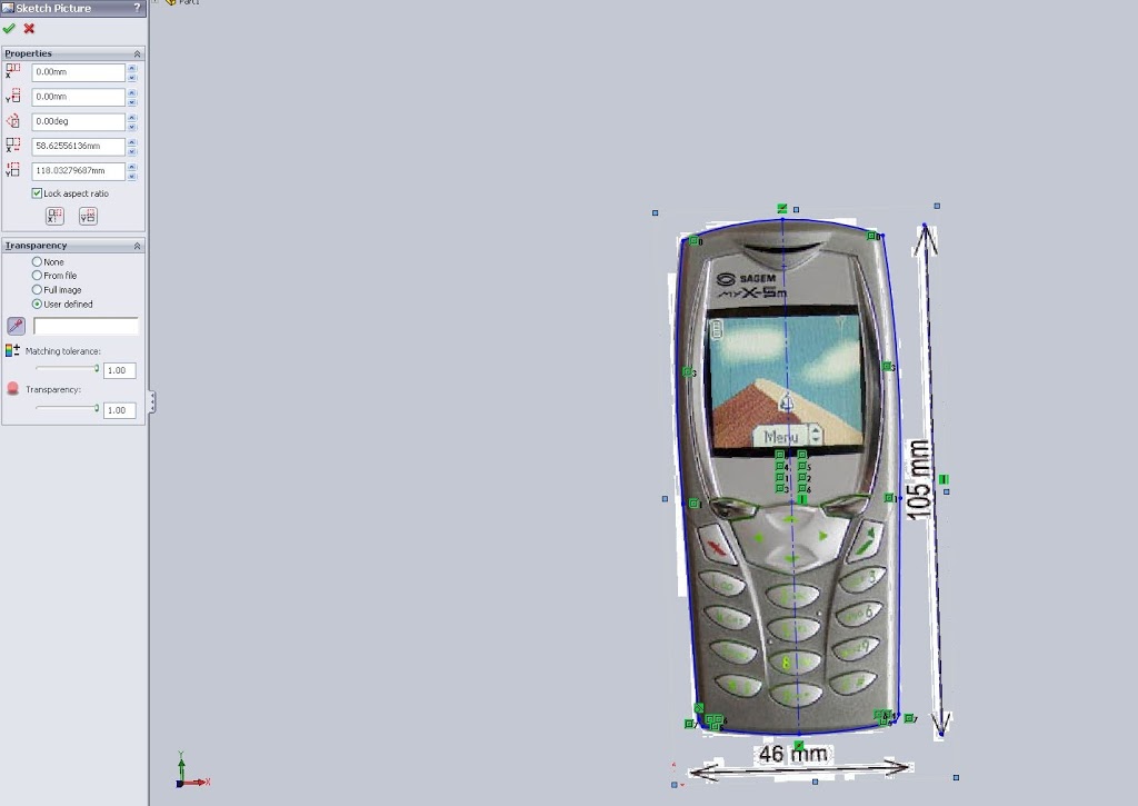 Note here I’ve turned on tranparency to eliminate the primarily white background. The next step is to utilize the picture to define the geometry. The front view can be done with a few splines. Here though I only modeled one half and mirrored the other half. For organic features where symettry is important using the Mirror command will save a lot of headache.
Once I had the top view I moved to the bottom. A reference line should not be necessary here. Instead the previous sketch can be used as a reference. (Note: Not using the previous sketch can cause design problems down the line as will be shown in later images). For the bottom sketch I decided to try another method. With the sketch picture inserted the AutoTrace function can be used.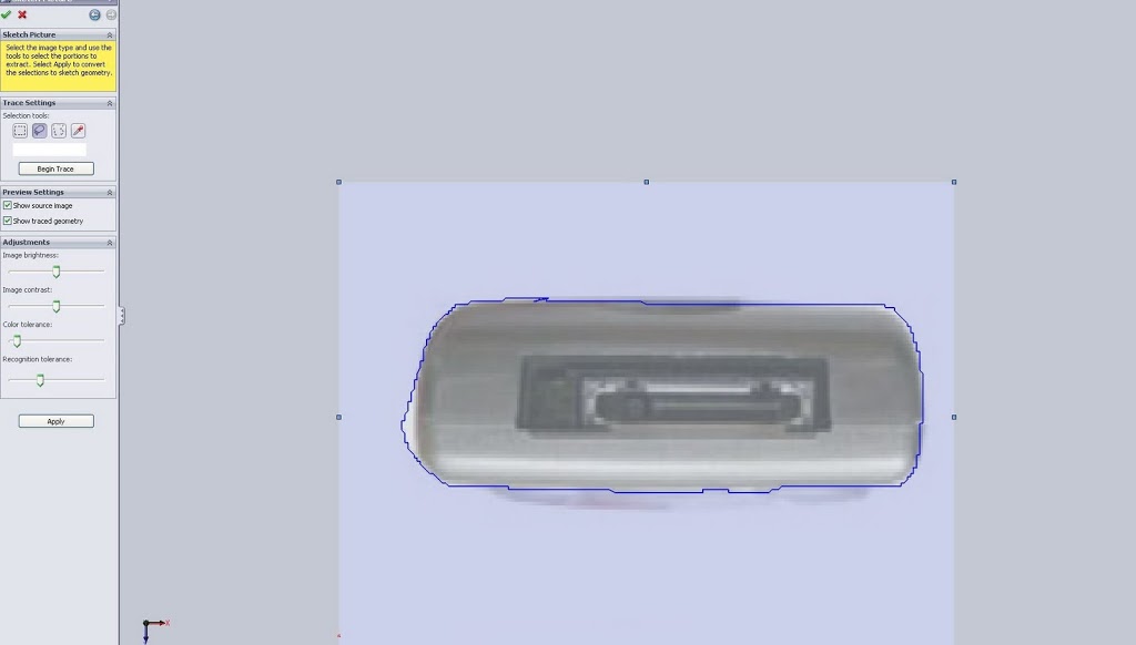
On this picture autotrace seems like it isn’t going to be the best option, instead I used some of the basic tools to model my outline. I didn’t realize till after but it’s important to see that the bottom view is not the bottom profile. Looking up the view contains the edges that stick out and the actual bottom is smaller than the profile of the image, again another reason autotrace was a bad option.
Regardless the autotrace function is intresting and has plenty of application for gathering the design intent pulled from freehand sketches, marketing images and the like. AutoTrace does have to be activated though in the Add-Ins menu (Tools>Add-Ins…). This is the same screen that will be used to later activate the Photoworks Add-In. However Photoworks is a robust add in and can eat up preformance so while I’m modeling I’ll leave it be.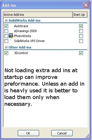 Next I modeled the side and top view, then it’s time to build some solids. I could use these views for surfaces but I prefer solids as they are more the focus of the CSWP. The first step is to extrude the front view giving a basic outline of the phone. Next up the side or top view. To test how this method works I jumped ahead (reviewing and fixing will be the next post). On subsequent extrudes though there is one key to note. The “Merge Result” check box should be cleared, the reason for this is built into the name “combine”.
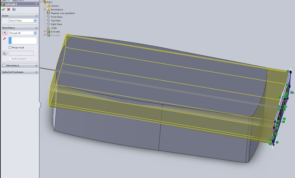
To combine bodies a model ust first have multiple bodies. Clearing the Merge Result box means this extrude will not merge with any existing portion of the model. Solidworks automatically adds a “Solid Bodies” folder to the feature manager tree (depending upon your settings this may always be present but empty) which will show how many bodies are present.
After extruding all three views I combined them using the Insert>Features>Combine option. I selected “Common” in the feature manager which meant that only the part of the model contained in ALL of my bodies would stay. Below is the result.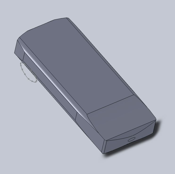
Looking at the above image the curves of the phone can begin to be seen, but so can the problems with this method. By only using simple extrudes most of the complex surfaces and curves failed to appear. To fix this I can go back and lock some of the geometry and utilize Lofts and guide curves which should give me the end result I want, but that will be another post.
If you have any tips, problems, or questions about how to model this portion leave a comment. Otherwise take a look at the next post to see how the design fares using lofts.