
When creating weldments one of, if not THE, most important dimensions is the length of each segment. Depending on the end condition (flat/butted) this may be the only value needed to actually manufacture the cut list of a given profile. For this reason the trim/extend tool is extremely useful.
If structural members are created in the same feature (using groupings) the software will automatically trim each member according to the end condition rules applied. However when items are created as separate features, either because they are different profiles or the work flow deems it necessary, the trim will not occur automatically.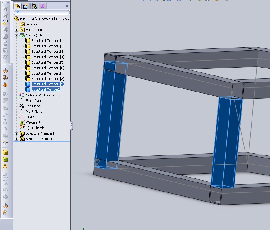
This image highlights two members. The one on the right has been created as a group in the feature “Structural Member1”, the trimming of it is already done. On the left is the member created in “Structural Member2”, as can be seen the profile has been extruded along the length of the path even though it over laps any members. It is important to understand when automatic trims occur and to verify this prior to production because at times the visual nature of the model make make it difficult to see the overlap.
There are a few selection options as to what surfaces can be used to trim a weldment. Items can be trimmed up to a specific face, which is the typical case for most profiles that will get straight cuts. 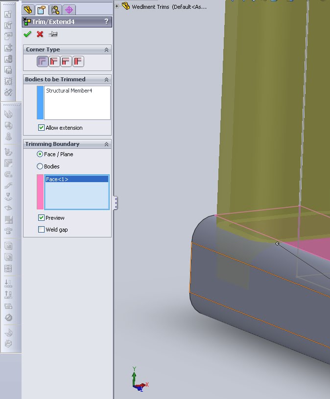
An almost identical result can be achieved by using a trim with body. This requires the total body to be selected, but here selecting a “simple” end condition will do the trick.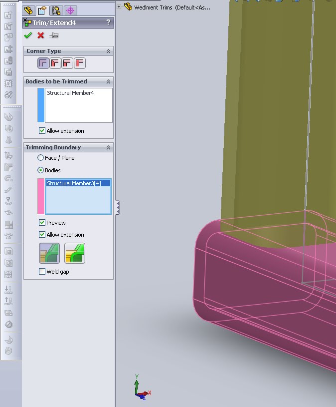 Trim works well enough, but in certain cases it will wind up extending a feature as well (see the tool name Trim/Extend!). In the below image horizontal member at the bottom initially does not come to a point, it is flush with the other corner. When using the Trim tool and faces the extension is added. This same issue appears many times when trimming corner member that will require more than one trim. Each configuration of corners will have a solution that is best and when in doubt the manual trim (see below) is always an option.
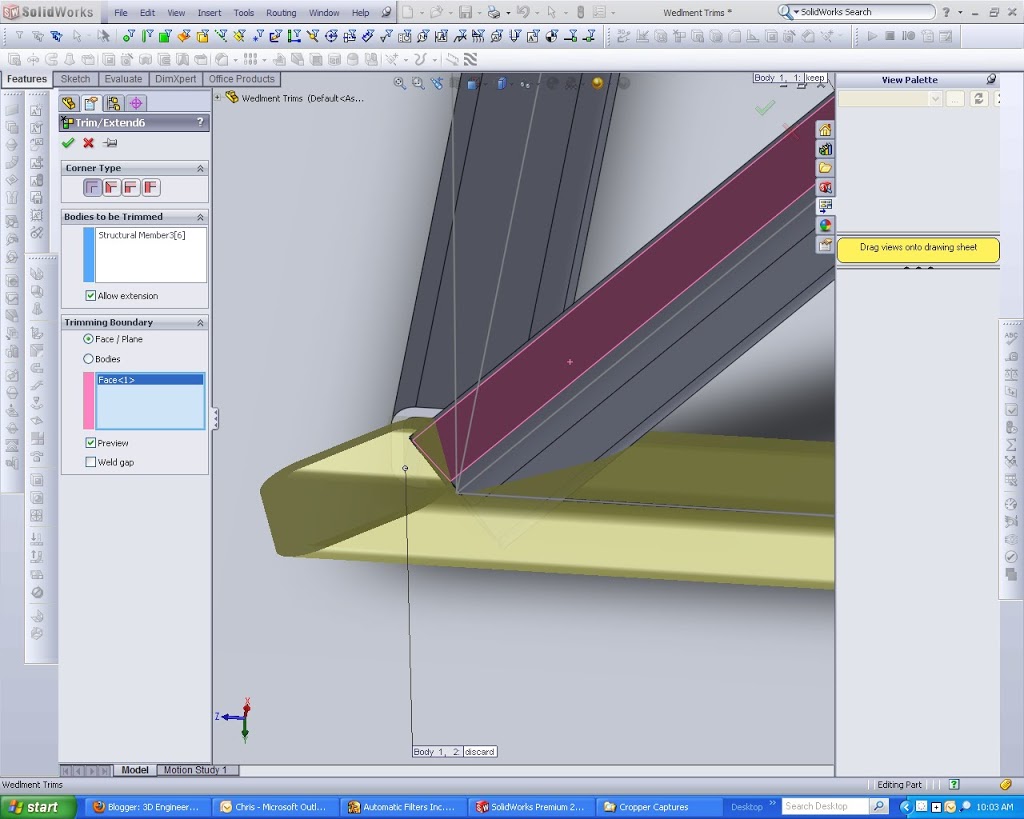
If however there is a need for a more complex cut, to help in welding or to show off the abilities of a cool laser cutter, a member can be cut using a body or with coped ends. This will provide a more detailed end and is essentially an “up to” cut or extrude.
If the trim tool is not getting the job done a cut can be created manually to trim a member. This is the same as any other cut but because it is a weldment choosing which bodies to cut becomes more critical. This is an option at the bottom of the feature manager for a cut, simply select the member or members needed and everything is taken care of. Even with an end condition of “thru all” the cut will only cut through the selected bodies.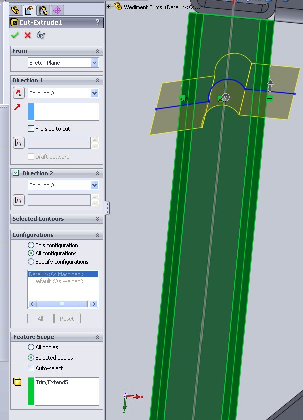
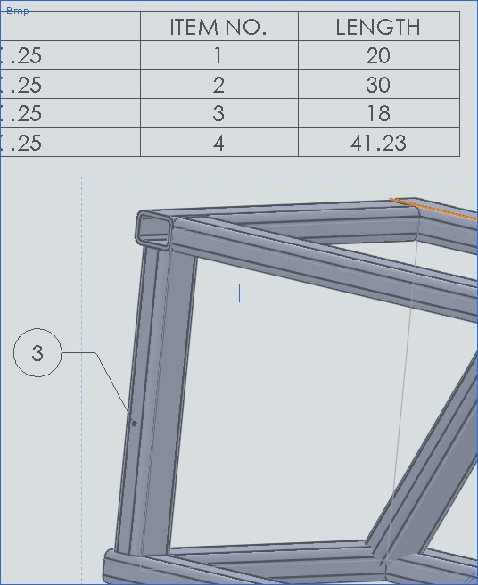
Cut list items are automatically linked to their length. This is a property that will show up in a drwaing and denotes the length. At a user group meeting recently the question arose as to what length gets pulled in. After doing some testing it seems Solidworks will provide the length as the maximum point to point distance along the normal of the profile. This is just to say it lets you know how long to make the initial cut. Even if the cut is curved as in the manual cut example above the longest segment is always the value Solidworks pulls in. Below are a few examples to show this.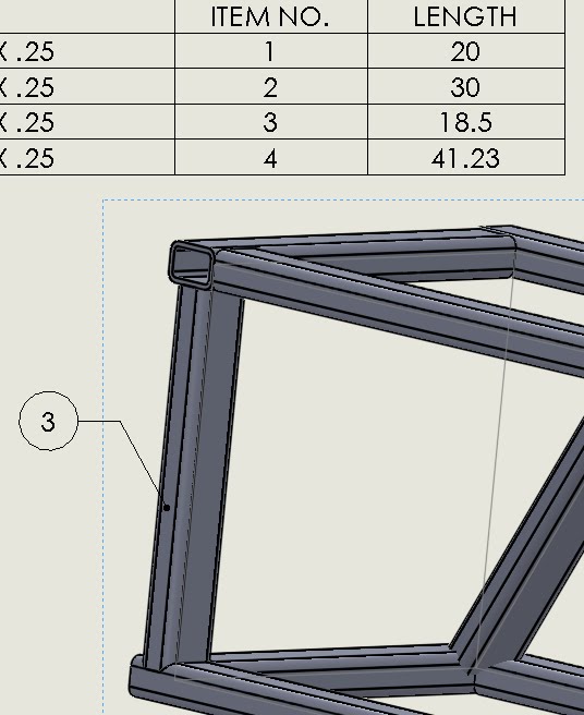 Above is the coped cut, below a simple cut. In the cut list table the length feature is obviously different. In this case the difference is equal to the radius of the corner fillet on the item as the coped member has to cover this distance as well.
This last example shows the same members but this time with a very awkward manual trim. The 15.81 is the value of MAX distance along the profile normal, ie from the furthest point of the circle to the flat face at the opposite end.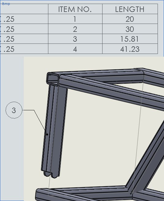
The cuts and trims are a basic tool but some of the more complex member intersections can cause issues. Knowing what each tool does can help create a proper cut, ensuring that a manufacturing cut sheet is accurate and no items will be cut too long, or worse, too short.
More details about the weldment tools can be found in the rest of the CSWP Weldment review overview.