
Need more rigid & flexible assemblies tutorials? Get SOLIDWORKS training online tutorials now. Get started with a membership.
One of the great things about SolidWorks is how easy it is to navigate through the assembly tree when working with an assembly containing multiple parts or subassemblies. Often times, you’ll find yourself in a situation where a top-level assembly consists of a set of parts and one or more subassemblies. In this case, you’ll notice that the general shape and mates of your subassembly will be in the same configuration as you’ve most saved them.
You’ll also notice that by default, these subassemblies are “rigid” in the context of the top-level subassembly within which they reside, even if they are “flexible” in their own assembly file. Often times, it is convenient to be able to move or place subassembly components in the context of the top-level assembly.
In this brief tutorial, I’ll show you how, and use a few pictures to illustrate this concept.
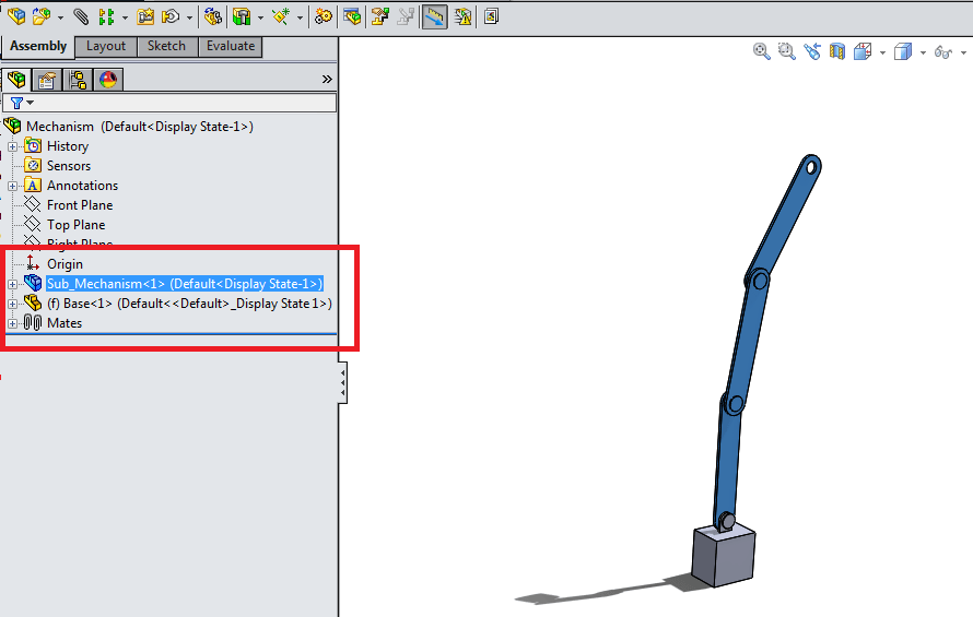
Let’s take a look at this example top-level assembly in the bottom figure. The top-level assembly consists of two “components” – first, a SolidWorks part document, defining the vertical stand, and second, a SolidWorks assembly document, containing a linkage and link mechanism.
At the subassembly level – that is, in the assembly file containing the linkage mechanism, one of the links is fixed in space, while the second and third link is free to move about the pivot point, constrained by the circular links. By default, we can use the mouse to drag and place the links at any angle we choose.
Now, in the top-level assembly, you will notice that wherever we have placed this links in space in their assembly file, it will show up as such here. Also notice that it is impossible, by default, to change the angle of these links relative to each other in the top-level assembly. This is because the subassembly is set to solve as a “Rigid” subassembly, by default. We can change this easily.
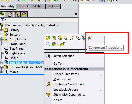
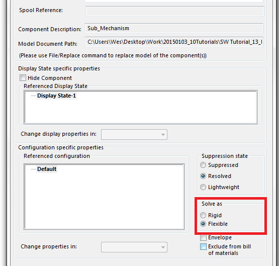
Simply right click on the subassembly for the linkage in the assembly tree of the top-level assembly. Select Properties. Select “Flexible”in the “Solve As” box as shown in the image below.
Now, notice that you are able to move this subassembly within the context of the top-level assembly. This is often very useful for manually checking the range of motion of subassemblies in your designs, or simply illustration.

When you’re done moving the subassembly, note that you can “freeze” it in place again by toggling it again to rigid in its properties. Notice that the icon for a rigid subassembly is different in the assembly tree than for a flexible subassembly.
Keep in mind that whatever mates are solved at the subassembly level also still apply at subsequent top-level assemblies within which a subassembly is defined. The mates are solved at both the top level and the subassembly level. In other words, if a mate holding the subassembly in place exists at the subassembly level, it will not be “overridden” in the context of a higher-level assembly within which it is defined.
New users often overlook this feature, but it can be a very useful and timesaving tool for arranging assemblies containing subassemblies. Good luck!
Check out more Solidworks Tutorials.
 |
| Solidworks 2010-2015 Training |
Get Certified in Solidworks or for more advanced users, or those looking to brush up skills without a certification, check out some of these tutorials and training courses.
Feel free to add any advice/tips/thoughts in the comments.
Need more SOLIDWORKS tutorials? Design with online training available 24/7.
Pingback: Best practices: Assemblies | CAD Booster
Pingback: Best practices: Assemblies – Peter CAD