
Ever cut yourself on the sharp metal edge of something? It’s annoying and can hurt really bad, luckily there is a feature that can be designed into your components to alleviate this problem. The Hem feature is an easy way to design out dangerous edges while also giving the vulnerable edge some much needed sturdiness.
There are a few design criterion with hems that mostly deal with what is possible within the constraints of the bending tools. Unfortunately these are more “rules of thumb” than they are actual design constraints as every forming tool will have different requirements. For example, when hemming it is generally required that the length of the hem be approx. 10x the thickness of the material. This allows enough space and stiffness for the bending tools to do their work.
Hems of course can be created in more than one way, for example a miter flange can typically replace the hem feature. Of the four basic hem profiles (Closed, Open, Teardrop and Rolled) each can easily be created as the profile of a miter flange. Here though, as is mostly the case, the preformance of the hem is better than work arounds using other features. At the same time though Solidworks can have problems creating mitered edges for a hem. 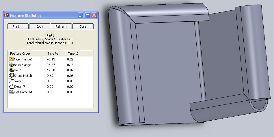
Above, even though the two features have the same profile and gap distance, the software chooses to miter the corners differently. The one of the right with an open corner is created by a hem. Even though the miter flange is clearly more resource intensive, designing the correct corner is more important and for that reason I’ve found that in most of my parts (and on the sample tests) the mitered corner feature will be the preferred route.