
Extrudes and cuts and go a long ways to creating some cool parts, but they can not do everything. I have always known about the Helix tool in Solidworks (Insert>Curve>Helix) but recently a few things prompted me to realize the limitations of Helix’s. The first thing that happened was I had to create a model that would have required a helix that curves. When creating a helix however it is only possible to do so in a single direction. Variable pitch and diameter option are helpful in creating more complex helices but still they are lacking. The second catalyst, which rang clearer, was a comment at a breakout session I attended at Solidworks World. In the Stump the Chumps session, which includes a who’s who of bloggers, power forum users, and SW employees, a question arose that could be solved using a helix. Charles Culp (the leader and guru of the Solidworks forums) and Matt Lombard (the Solidworks Surfacing Bible author) both agreed that using curves was NEVER the answer. Charles stated that any time he creates a helix his next step his to create a 3D sketch hit convert entities, turning his curve into a 3D sketch. Matt seemed to think any curve required can be created using surface tools (surprise!) and that these surfaces are more predictable and more easily controlled. So, let’s see what all of these options are.
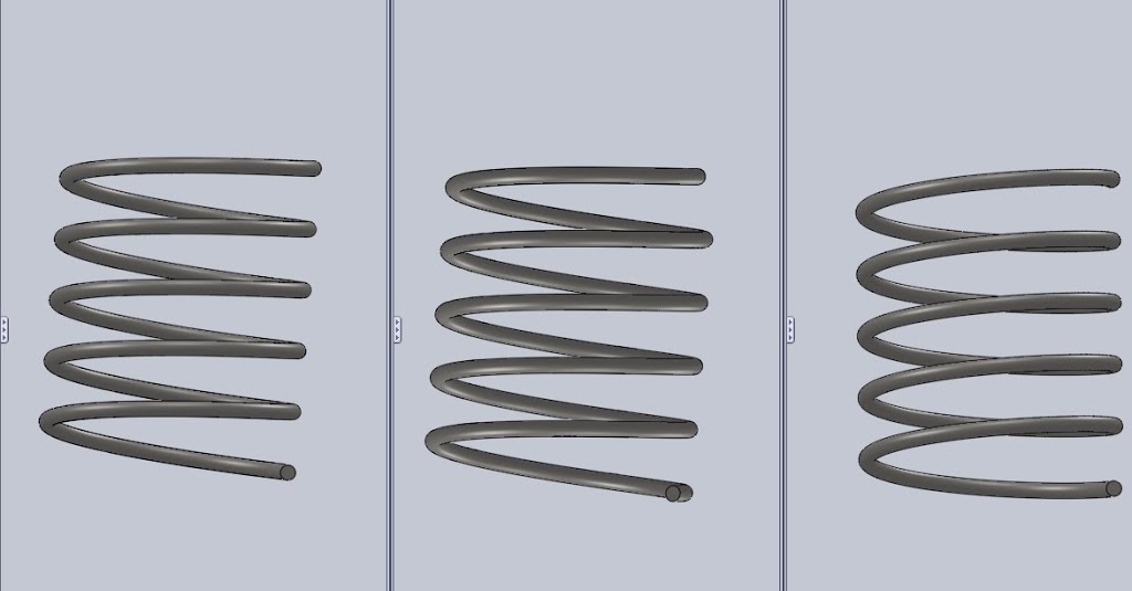
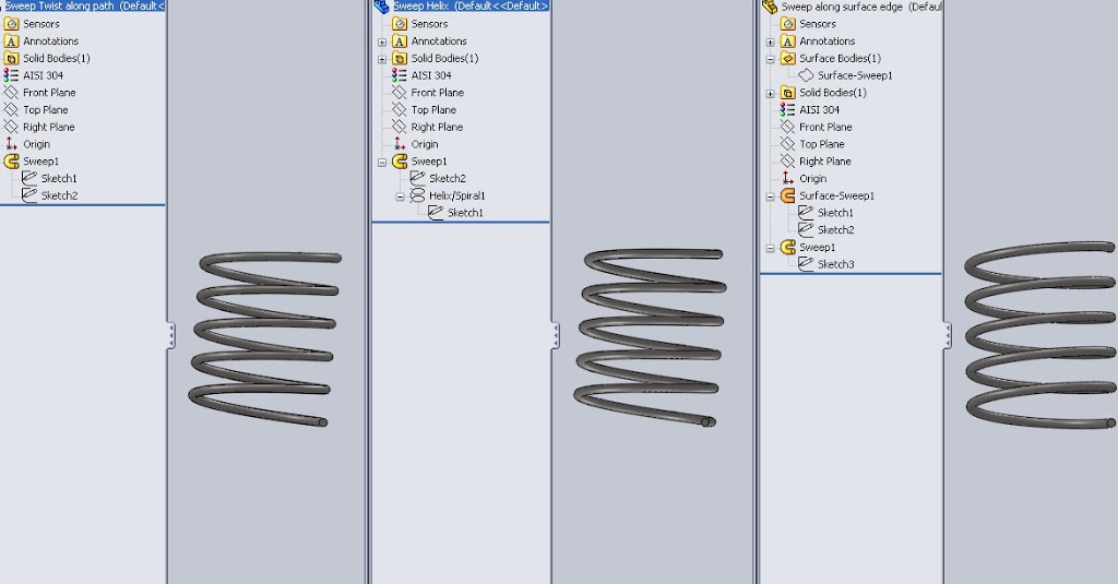
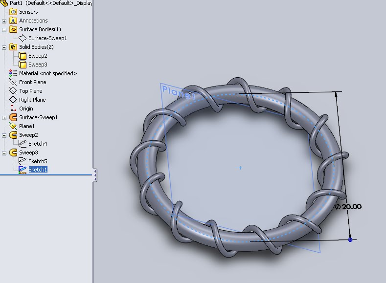
So how are these parts different, in the method of creation of course. The image below shows the expanded feature tree of each component.
Method 2 (center Fig 1): Sweep using helix as path. In the video I have already set up the helix at a 270deg start angle to ensure that my profile sketch on the right plane will piece the helix at the end point. A 3D sketch would also solve this problem if I didn’t set the angle correctly, but we can see here where Charles and Matt may take issue with curves. You do however get to create the path of the coil, and visually seeing it before creating is helpful.
Method 3 (far right Fig 1): Sweep using surface edge as path. Create and view the path of the profile, check. Easily locate the profile on the vertex of the surface, check. By creating the surface and selecting the edge at the path more folders are added to the tree to deal with the surface body. This is an easy fix, simply select and hide the surface after the fact, unless you like looking at the fun slide-like geometry. This option is the most resource intensive but also the most predictable and as things get more complicated this work flow looks like a great option.
Curved Coils
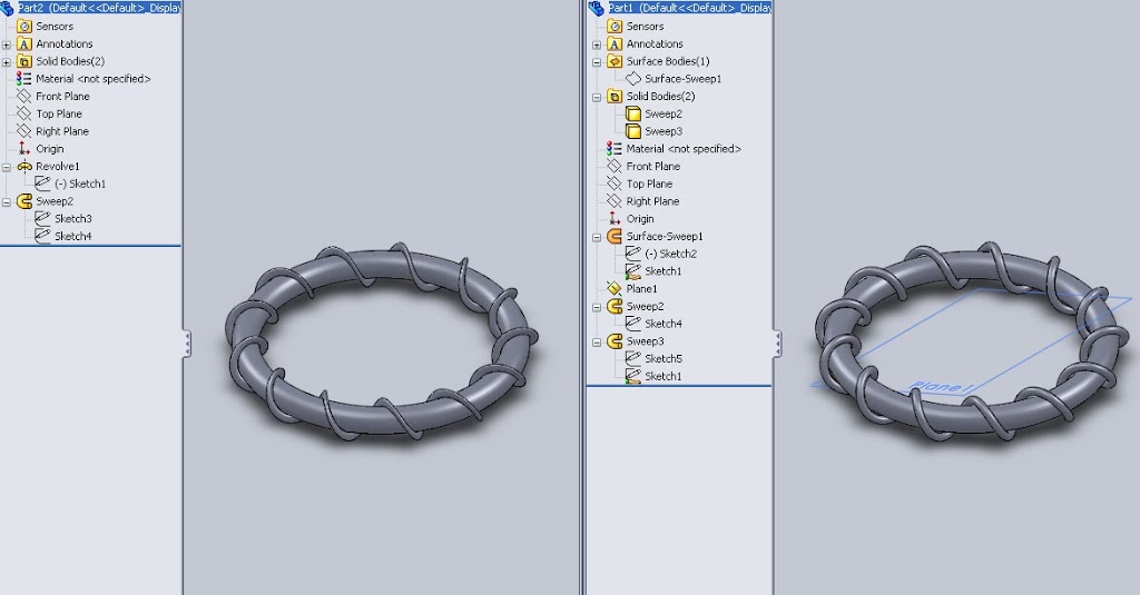
The issue I was having initially was that when creating these curved coils my original work flow always caused my profile to get compressed. Unless the profile is kept normal to the path it is sweeping over this “smushing” effect kept occuring. The “twist along path normal constant” sweep option was not helping any. Below is a visual of what was occuring.
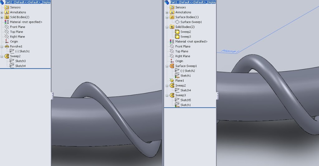 On the left, my initial sweep work flow was getting smashed. Using the existing surfaces it was simply guesswork (or rather, a severely complicated hand calculation) to be able to get the profile in such an orientation that it would stay normal to the sweep path. On the right, by using the surfaces to create my path it gave me the ability to add a plane. Once the path was created I added a plane that was normal to the path at a point, than it becomes possible to have the profile piece the path at a normal.
Step 1: Start out by creating a single circular sketch. This will be the major circle around which everything happens. Mine is dimensioned to 20 inches.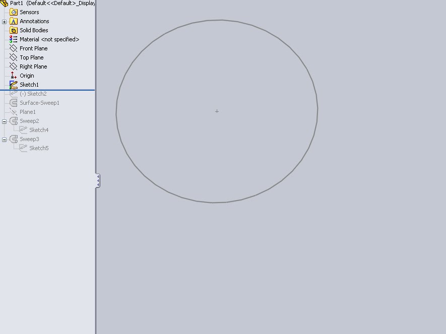
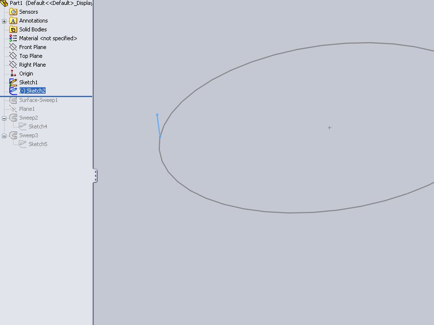
Step 2: Next create a line segment on a perpendicular plane. Make sure the the end of the line segment pierces the original circle.
Step 3: Insert a surface sweep. Use the line segment as the profile, and the major circle as the path. Under the “Options” select Twist along path. Insert the number of twists required. Mine is arbitrarily picked at 13.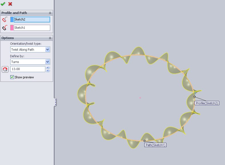
Step 4: Next insert a plane. This will be used to sketch the profile of the coil. For my relations I selected the edge of the surface and made the plane perpendicular. I also selected the origin.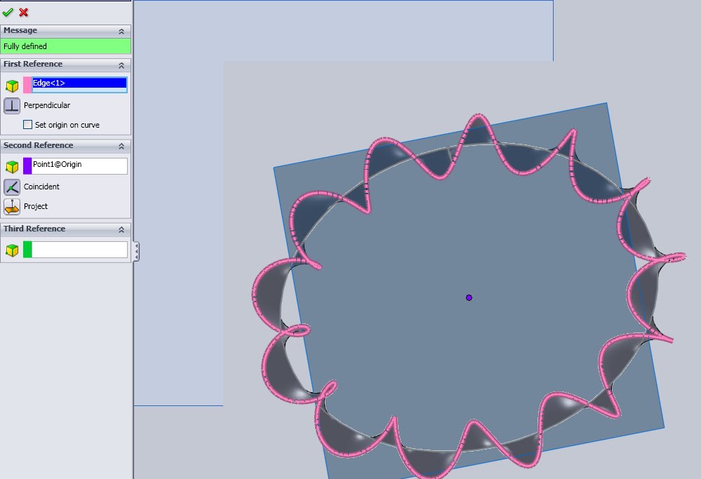 Step 5: Below the plane is now inserted.
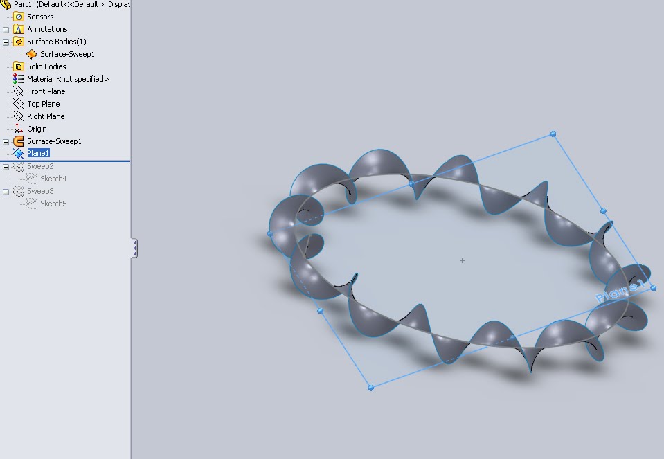
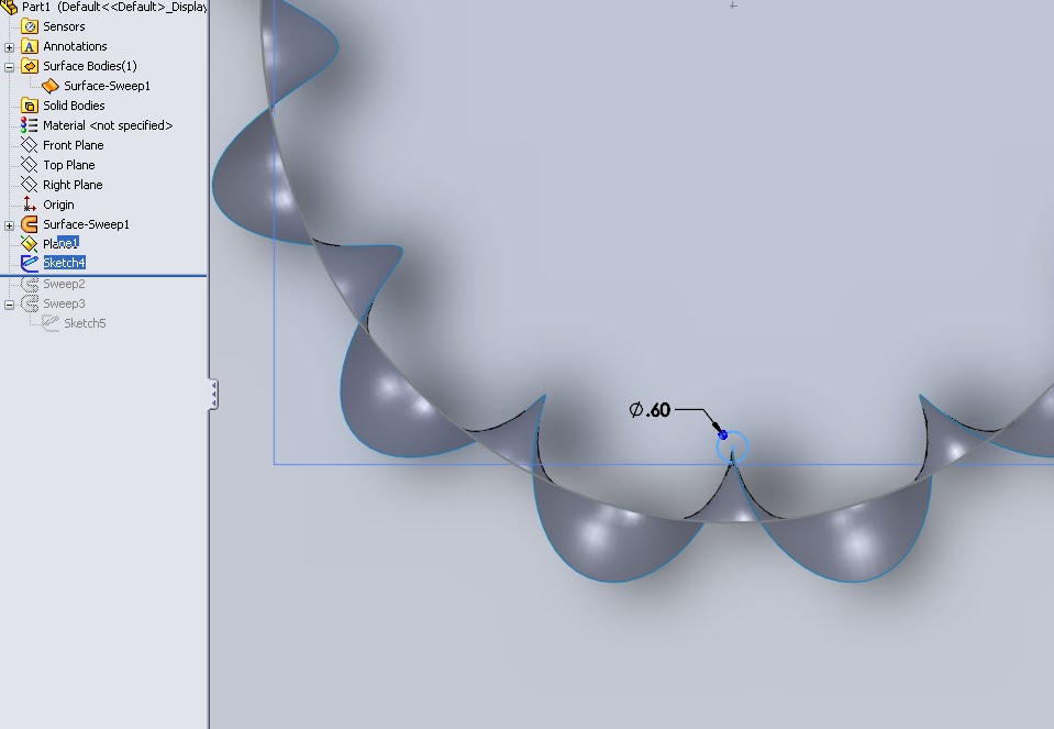
Step 6: Select the plane and start a sketch. Draw a small circle and dimension it with the coil wire diameter. Select the center of the circle and Ctrl-Click the edge of the surface. A property manager will come up to add relations. Select Piece. Because the plane is perpendicular to the sketch surface this means the center of the whole is pieced perpendicular.
Step 7: Insert a sweep feature. Select the circle profile created in the previous step as the profile. Select the surface edge as the path. The perpendicular pierce relation will be maintained along the sweep path keeping the profile perpendicular to the path at ALL points. This is key to not “smushing” the resultant coil.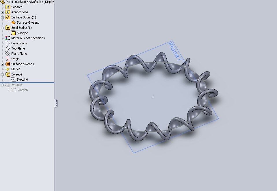
Step 8: The Surface body still remains. Locate it in the feature tree.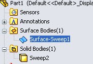 Step 9: Right click on the surface and select “hide”, the icon will now appear clear.
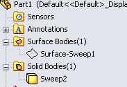
Step 10: Finally I created a final sweep to add perspective to my images. I created a new profile but used the same path from step 1.
The same theory can be applied to many sweeps. A further look at the surfacing tools will help to create more intricate surfaces edges that can be used as paths.
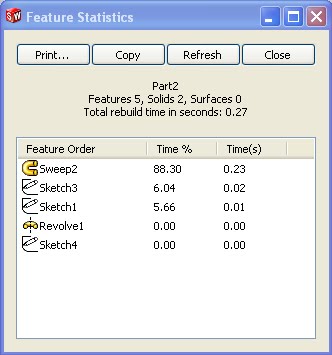
The above image shows the statistics on the rebuild of the “smushed” coil seen in the left panel of Image 2 and 3.
Below is the rebuild for the coil seen in the right panel of Image 2 and 3.
Fig. 3: Statistics for Sweep using Surfaces for path
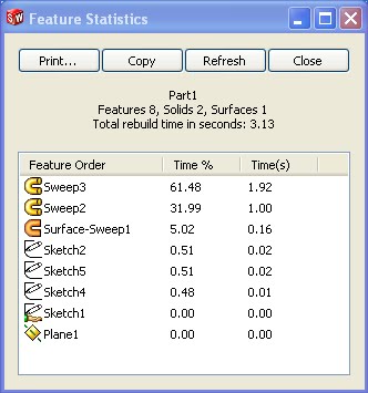 It is then obvious that, as expected, using surfaces significantly increases the rebuild time.
Note: It was announced at Soildworks World 2010 that Solidworks 2011 will contain a feature that allows a user to lock a model along the feature tree to prevent the entire model from rebuilding. This “feature lock” tool will greatly impact the ability to quickly make changes to complex models.
So all of this surfaces business is fun, but that’s not to say the simple helix option should be completely ignored. The ability to have variable pitch and diameter helices is a powerful tool and can go a long way in simplifying a design. Many standard springs can be created using only a single helix feature and a sweep. Add in a powerful design table and there is essentially no reason to even open a file to create a new spring.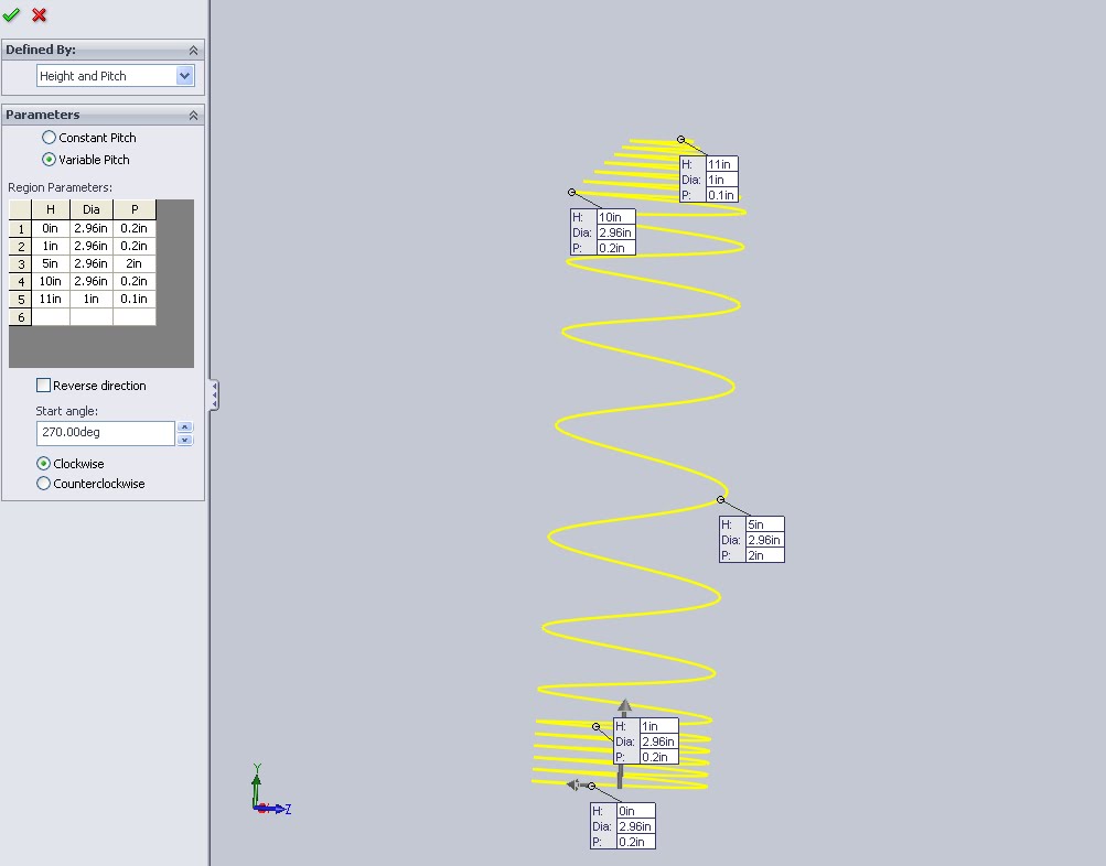
Above is an example of a variable pitch (and variable diameter) helix. Playing around with the settings here is a good way to figure out what can be done. I’ve actually seen something similar to this sweep in a consumer device. The application I am thinking of was a water bottle that had an obnoxiously long straw that encircled the container.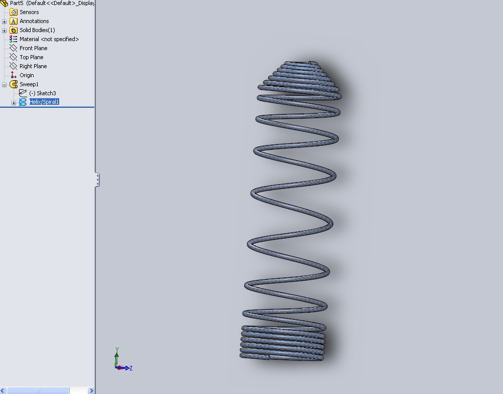
I could fill another twenty minutes of scrolling texts with more examples but they would all boil down to the same basic principles. If I missed anything here feel free to drop me a line as I truly am looking for all the ways to create coils and I would love to add some more content.
Could you show how to make a coil that increases in radius? (kind of a tornado shape) I’m trying to model the coil within a hairdryer on Solidworks
I think I understand your goal and if so the easiest way to do a coil in increasing radius would be with the Surface edge as path (Video 3 above). The video shows how to create an initial surface but if you did a quick surface cut and created the surface in a cone shape then the edge of the surface would be a tapered coil. Leave a comment with contact info and I’ll get more details for you.