
A curved edge flange is very similar to the Linear edge flange. Select an edge, or multiple edges, and enter some values. Here though you are a bit more limited in the geometry of in “Edit Flange Profile.” The profile sketch is only allowed to contain the flange edge and the profile of the flange. Because the edge is curved this sketch will be a 3D sketch and thus drawing holes into the flange sketch is not allowed (in the Linear edge flange adding geometry to this profile can improve performance).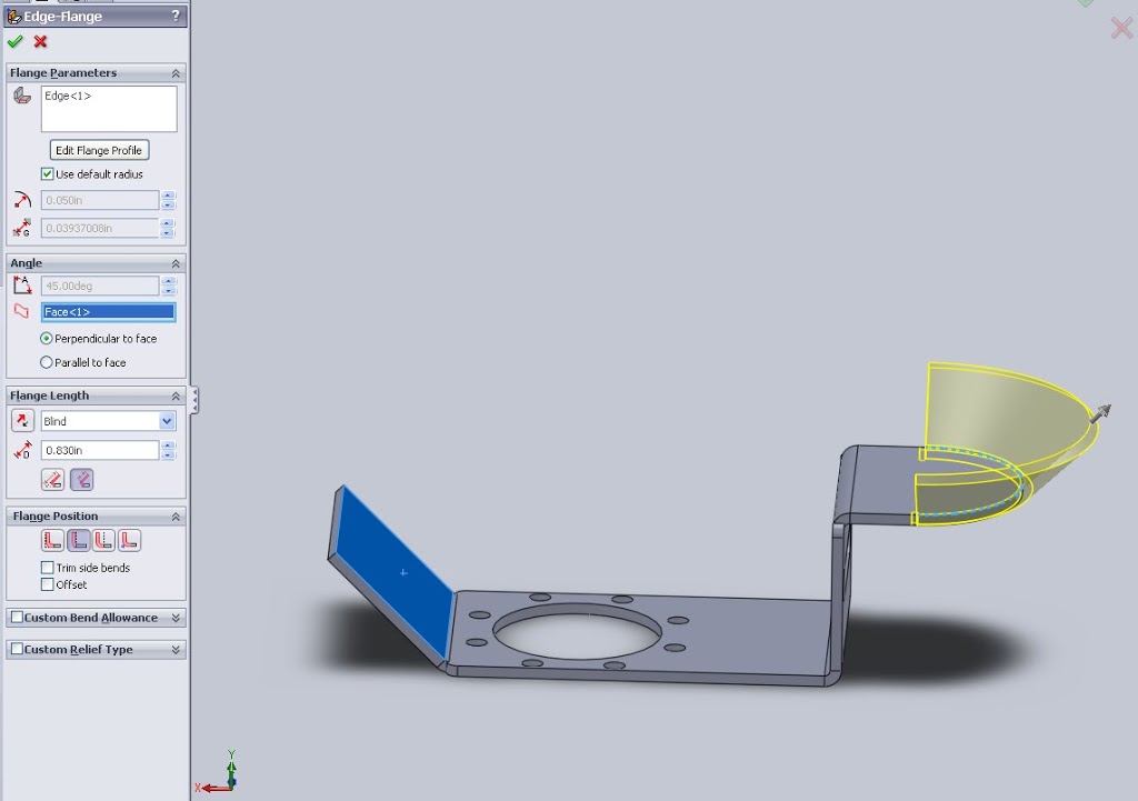
Even though this feature is rather simple, there are some details which are important both from a modeling and manufacturing standpoint. The first few items (Radius and Gap Distance) are essential but mostly only need to be entered once per part. This is because the Base Flange function creates a feature that stores this information.
The flange angel is also easy to determine from prints, drawings or models and can be put in just as easily.
The next feature is a little tricky, Flange length, this is due to how the feature can be measured. Length can be measured from the inside or outside edge of the radius and the difference in the two is obvious (see animated .gif below).

On prints this should be dimensioned in the same way the icons in solidworks are shown, in measuring though this can be difficult with calipers or rulers. If accuracy is paramount getting the correct value of a “Virtual Inner Sharp” is nearly impossible as it is difficult to determine where the bend of the material actually starts. Although a machine shop with good communication skills will get clarification on these types of values, if they are ambigious, not all will and you can be left cutting down or scrapping whole lots of components.
The same issue appears on the flange position, what may seem like a simple selection during modeling can greatly effect fit. Generally having an error here will cause measurements to be faulty by a value relating to the material thickness. For 12 guage steel that’s .105″, multiple by a second wall and a simple enclosure can be off .21″ (get a full guage chart for sheet metal on the web). What’s more any items dimensioned in relation to the walls can also get screwed up easily during fabrication. Imagine designing a nice little encolosure for a circuit board and realizing that all mounting holes are out of place by nearly 1/4 in, not good.
Take the time to talk with a fabricator about how they prefer to see a print (everyone has different opinions here) and make sure if there are issues to explain them in notes on a print. Even engineers with a thorough understanding of GD&T practices will appreicate an extra note if it saves them losing a batch of parts.
Great info, thanks. Wish I would have found this page 2 hours ago!