First thing is first when working with weldments, creating the structural profile. Essentially weldments are bars, pipes, or lengths of items that maintain a standard profile and attach to each other (often via welds). The software comes with a few standards but the exam, and my needs, require making your own. So how are weldment profiles created?
Open a new part and save it as a library feature to the weldments profile tab. File>Saves as then select a library feature part .sldlfp. You may need to back out of the directory and find the data/weldment profile folder. Save the part as a name that will make sense as a “Size” because when selecting a weldment this will be the notation.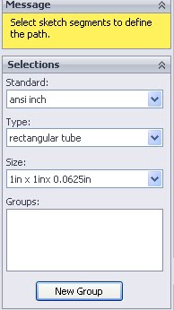
Here the weldment data folder is the top level. “Standard” is the first level of sub folders. “Type” are sub folders of the standard. Size is the file name. Unfortunately I’ve found no way to integrate configurations into weldments. This would be extremely helpful as then design tables could be used to define a variety of sizes without requiring the manual creation of each profile. Guess this will just have to be a feature request.
I like to do all of this prior to starting any sketching because occasionally when saving to the library the software dumps my data while giving a message like this .: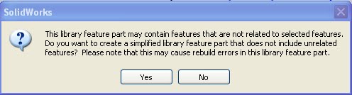
Once the file is saved then I go ahead and create the profile. This is an easy step that involves sketching but a key to weldments is how the weldment is located in your files. To assist down the line it’s best to start putting in construction geometry that touches any point that may be used to locate the weldment. This sketch makes it possible to orient the resultant weldment by any of the sketch corners, side midpoints, or center of the weldment.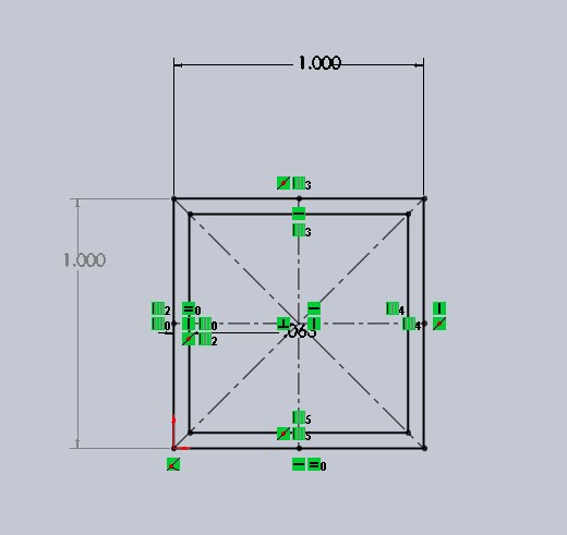
After creating the profile I also needed to right click on the sketch and select “Add to Library”. If this is not done, when adding the weldment to a part this error occurs (Library Feature is empty):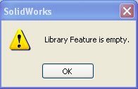
Once the library feature is added some other changes will occur in the part. First the sketch icon in the feature tree will change from this:![]()
![]() to this:
to this:![]()
![]() . Once the sketch is denoted as a library feature its dimensions will be added to the dimension folder of the feature tree. The dimension folder is one of two folders added to any library part, the other is references. Because library parts are used to build other components these dimensions and references are specially noted to make orienting and placing the library feature easier/more intuitive.
. Once the sketch is denoted as a library feature its dimensions will be added to the dimension folder of the feature tree. The dimension folder is one of two folders added to any library part, the other is references. Because library parts are used to build other components these dimensions and references are specially noted to make orienting and placing the library feature easier/more intuitive.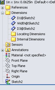
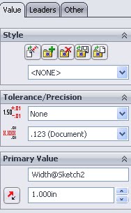
Dimensions can be added to the locating or internal dimension folder by dragging and dropping them within the feature manager. To change the name of the dimension you can edit it in the dimension feature manager: Primary Value (edit a sketch, double click a dimension and this box appears)