
Despite the recent addition of Instant 3D and a number of free form deforming tools most Solidworks models begin with a well laid out sketch. This is true too for the CSWP exam. Laying out a sketch in the wrong fashion is the easiest way to make a costly mistake.
The first step is understanding the basic tools. The built in solidworks tutorials (30 Min lesson, 3D sketching) cover most of the basic. Starting a sketch, creating circles, offset, construction geometry, dimensions, hole wizard, fillets, 3D sketching, patterns and more. Most other sketch tools can easily be learned by selecting it and clicking the ? in the resultant feature manager.
There are also a few tricks that can help with the workflow of things.
Grid: Solidworks is good at having features automatically snap to relations. Horizontal and vertical lines, edges and points snap to coincident. This can be both misleading and wrong given the inaccuracy of the pictures in the CSWP. Sides that look to be co-planar in the exam question figure may be just that, but they may change in future questions. I find that having a grid available helps lay things out with proper relations while still making sure the realtions do not overdefine or improperly define certain edges.
To turn on the grid check the box at(Tools>Options>Document Properties> Grid/Snap> Display Grid)
To enable snap to grid check the box at (Tools>Options>Syctem options>Sketch Relations/Snaps> Grid)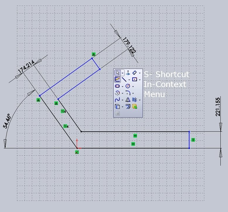
S key and RMB in-context menus: The single biggest time saver in newer version of Solidworks is the addition of in context menus. The RMB (right mouse button) brings up an in context menu that can be customized from a limited list. This is very helpful in flying through a quick sketch and eliminates the need to get the mouse back up to the tool bars. Even more powerful is the S key which brings up a shortcut menu of actions typically used in the current state and it can be customized with anything. Not only can the S key access all the sketch features needed it can also be customized to add such items as Extrude and Cut, the two most commonly used features following the sketch tool. Although the movement of the mouse to the top of the screen might seem like a small thing to eliminate over time this ligtning quick access to any needed feature can significantly reduce the time spent looking for items.
Full defined sketches: Making sure a sketch is fully defined is simply good practice. Under defined sketches cause major problems when changes must be made, arcs over extend, lines cross, dimensions loose defining vertices, and features fail. It is much easier to go back and remove definition that it is to painstakingly correct each error caused by an under defined sketch. For visual purposes a fully defined sketch or sketch entity will appear black while under defined entities will appear blue. Once your sketch is complete click the RMB and get the in context menu. This will include an option for “Fully define sketch”. A property manager appears and allows the user to select the entities and relations to be defined.
Variables: Because of the nature of the CSWP where a single model with only a few changes can make up 3-4 questions it’s important to allow read ahead and plan for future questions. Typically an exam model will have a few variables labeled A,B,C, D. Each question will ask for the center of Mass given different values of A,B,C,D so being able to quickly switch the values can save valuable time. One easy way to setup these variables is to simply use equations. This way the sketch dimensions can be set to equal “A”, “B”, “C”, and “D” even if D applies to 4 values only one value, “D”, must be changed. Making a single change is easier than fixing every instance of the value and again eliminates issues.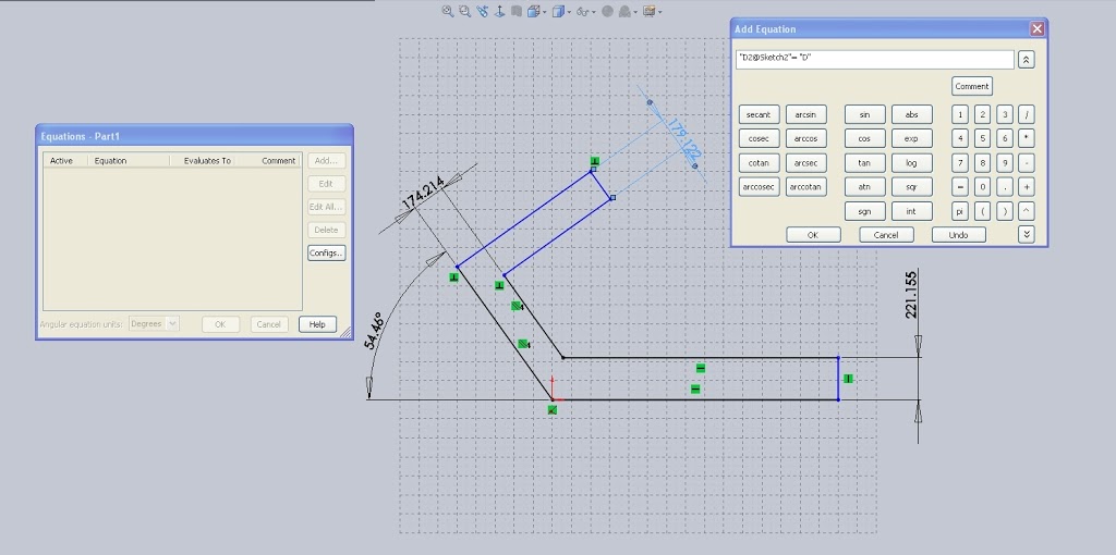
To set a variable using equation is a two step process. First the variable must be defined. To do this select Tools>Equations. This brings up the equation manager. Select “Add” and then simply type
“D”= X
X should represent the value of A.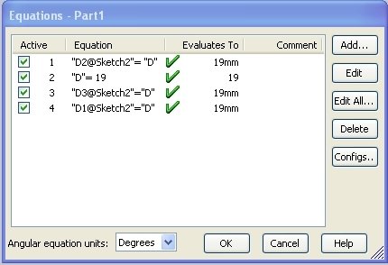
Next “D” must be linked to a dimension. Again select add then select the dimension, the default format should be similar to “D3@Sketch2”. This is the “Primary Value” of the dimension and can be changed in the feature manager of the dimension tool if necessary. Then simply tell SW what you want this value to be. In this case “A” the resultant equation is a rather simple
“D3@Sketch2″=”D”
Now to change the values for questions 2-4 simply change the equation for “D” and all instances will be changed.
As is usually the case in 3D cad there is more than one way to handle organizing a design and layout and each is user. If anyone has a better workflow for laying out these variables input is always welcome.
For now the tutorials and these tips will be all that I’m overviewing for sketches. Of course, as mentioned earlier, sketches are the corner stone of the Solidworks package so further review will be a part of all other studies.