No, Solidworks is not testing your ability to pitch a softball. The K-Factor for sheet metal is a variable used to define the neutral axis of bent material.
A bend creates two types of stress on a material. Compression on the inside of the curve (creating a shorter inside distance) and tension on the outside of the curve (where the material is stretched longer than it’s original).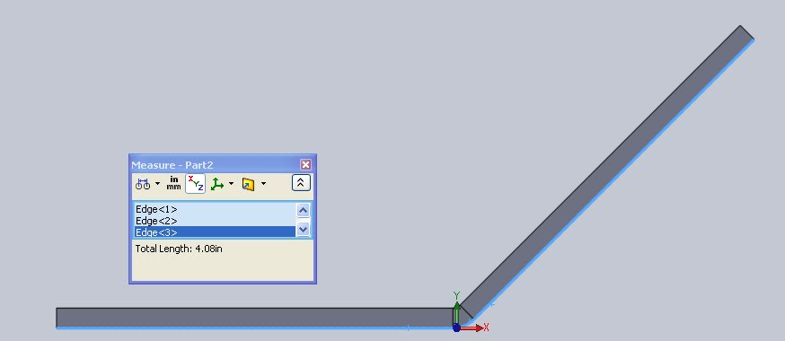 Zoom in on the above picture and you’ll see that the total length of the flanges and bend on the outside is 4.08″. Below the total length of the flanges and interior bend is 4.00″.
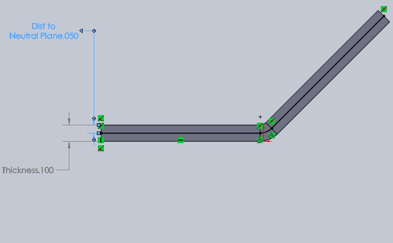
 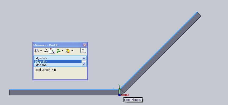 This seems obvious except when you consider that this piece starts out as a single flat piece of material with the top and bottom surfaces being identical in length. This means the material deforms when bent (due to the stresses mentioned above) but there is one cross section of the material that stays at equal length. This is called the “Neutral Axis”. The relationship between the distance to neutral plane and overall thickness defines the K-Factor.
K Factor is used in defining the bend allowance, thus by using bend allowance tables it is possible to automatically set the K-Factor for defined materials (See gauge tables). Standard K-Factor’s can be found from your sheet metal supplier, online, or through real world testing. It is only one of the ways bend values can be determined. See the others.
Bend Allowance
Bend Deduction
Gauge Bend Table
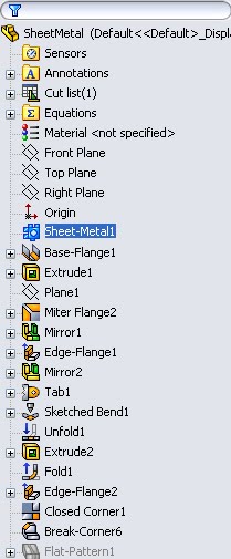
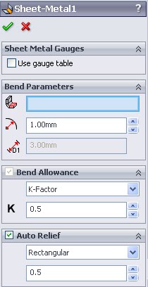
I’ve spent some extra time looking at these values because a changing K-Factor appears as one of the questions on the CSWP Sheet Metal Sample exam provided by Solidworks. To change the value for the entire part just select the primary “Sheet Metal” feature and in the property manager for Bend Allowance select K-Factor and enter the value.