
 It is a simple fact that weldments are not going to just be made up of members. Welding can create a strong bond, yes, but there will also be a need for bracing to transfer the loads correctly. To do this many beams get cross braces of smaller sizes or just a simple gusset. When it comes to the basic gusset Solidworks again has a built in option. Insert>Weldment>Gusset or the Gusset icon on the toolbar will both get things started.
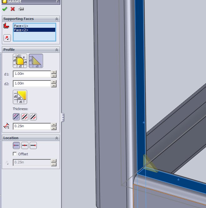
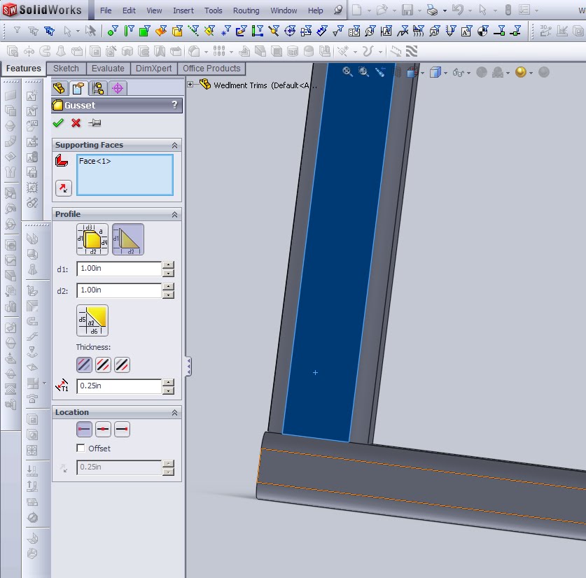
 Above I have selected two faces, between which I would like a gusset placed. Usually this is two opposing faces to a member, but it is interesting to note here that the gusset feature does NOT require a part to be a weldment part. Gussets can be added even to normal parts that contain no weldment information of features.The criterion for faces is that they can no be coplanar (ie. 180 degree between them) and they must interesect. So again even on non weldment parts a gusset can be used, though ribs will accomplish most of the same tasks and seem to be a better work flow.

There are some dimensional options that can then be specified for each gusset. Length and height are fairly straightforward, as is thickness. The location on the other hand can require a few clicks to get the right orientation. Above is a gusset which has a location of centered. It is clear from the image though that the gusset falls to one side of the center, this is because of the select box of it’s thickness.
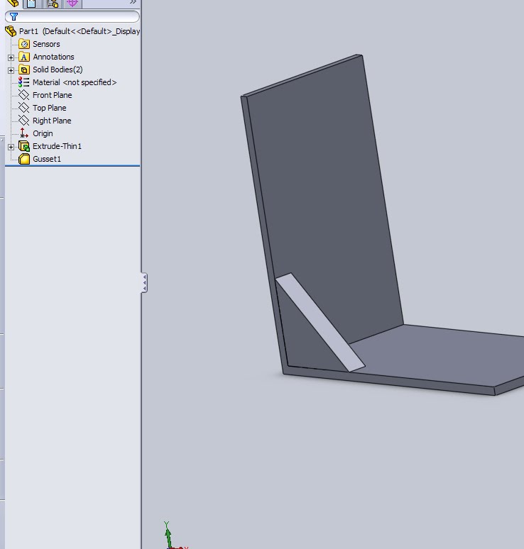
In this image the thickness is constructed as a mid-plane which properly centers the item. If the driving sketch were turned off, or the gusset was viewed from an angle other than perpendicular it would be easy to make this small mistake. In the case of the CSWP where the center of mass is usually requested a few small errors like this could make a passing grade drop to a failing grade.
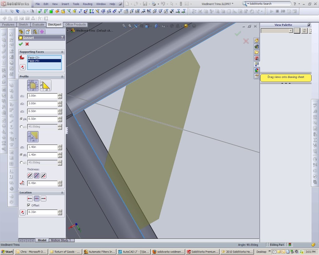
One of the other options for the gusset is the internal chamfer. Here is is simple to select the option and reveal the other value boxes in the feature manager.
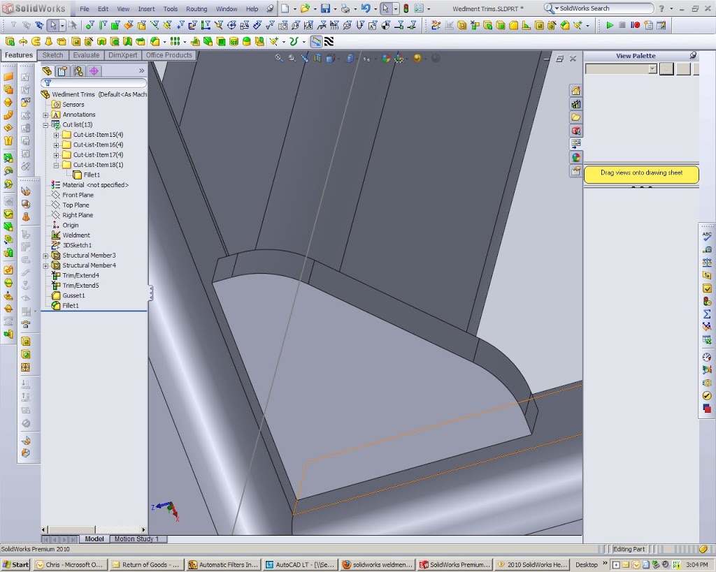
Of course, not all gussets will necessarily be simple triangles or gusseted. Though those designs tend to be used due to their ease of manufacture some other functions may be preformed. When another function is preformed on a gusset it will change the name of item in the weldment folder manager. If for some reason a cut/extrude/fillet was added the item will no longer carry the Gusset name unless the cut/extrude/fillet is renamed to read “Gusset”. This is a minor detail but knowing how names propagate to the folder manager can help to trouble shoot problem parts. (items are always named after the last feature to modify them)
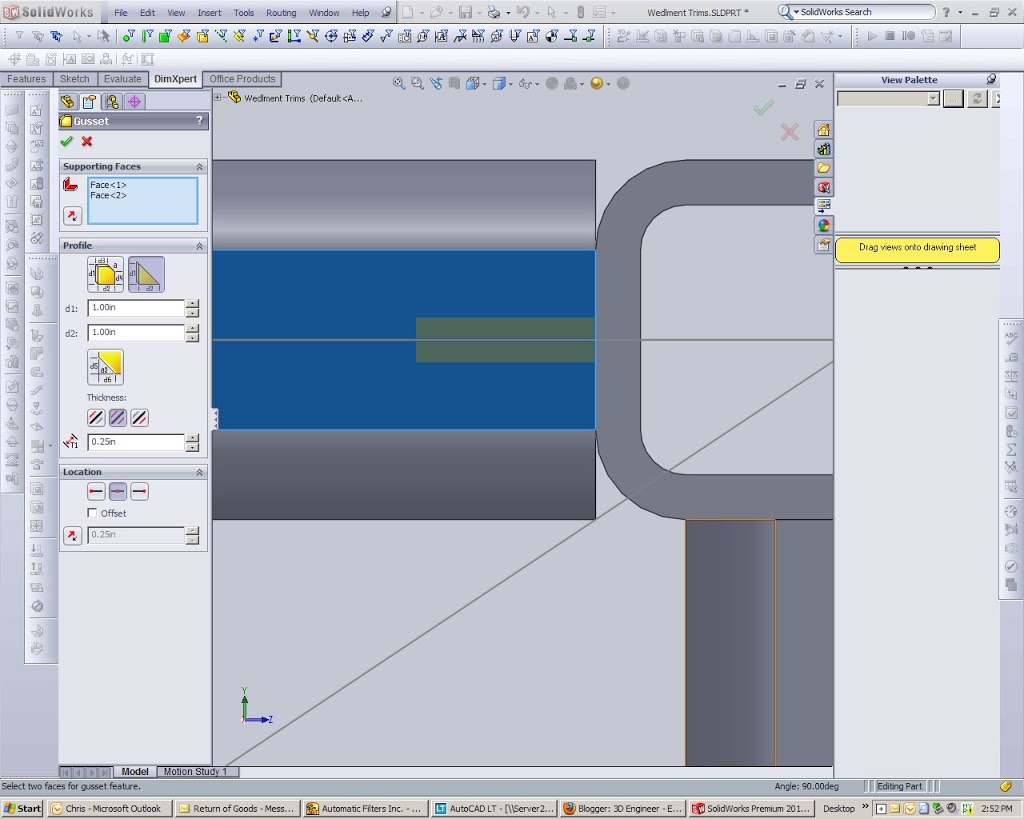
The last thing to note on gussets pretains again to what they fail to do. Gussets on some members will extend on the outside of a joint and cover an entire joint. This can be seen on bridges or large trusses. Rivets are used to attach the gusset and by putting them on the outside of all members the load can be distributed more evenly on the member. These types of gussets can not be created with a gusset feature. In the above image I have tried to select two faces to show this and clearly the option fails. There are a few workarounds to this, a user can create an outside oriented gusset and extrude/move the faces as needed. Or to simplify the process a manual gusset can be designed. simple extrude a new feature off of one of the faces in the profile required. If the part is already a weldment this new extrude by default will create a new body, then simply rename the extrude feature to say “gusset” and due to the naming system it will appear in the cut sheet as such.
This is just a basic overview of the gusset feature. More reviews on other weldment items can be found through the CSWP Weldment review post.