
Choosing how and where to start and end solidworks features can significantly impact the design intent of a model. Although there are numerous start and end conditions in general, the selection criterion on a feature by feature basis is very specific and surprisingly intuitive.
The easiest way to review these is by example. For the model on the sample test I opted to build the side profile first. In this way I was able to maintain most of my geometry in a single sketch. However there was a curved portion that I modeled as a second sketch. To do this I highlighted the face, right clicked and selected sketch. This “start condition” is then the face selected. If this face is eliminated errors will occur.
Because my base sketch of the first extrude contains this line I know that this face will be built anytime the base sketch is unsuppressed. Making this sketch on the face causes it to be a “child” of the first sketch.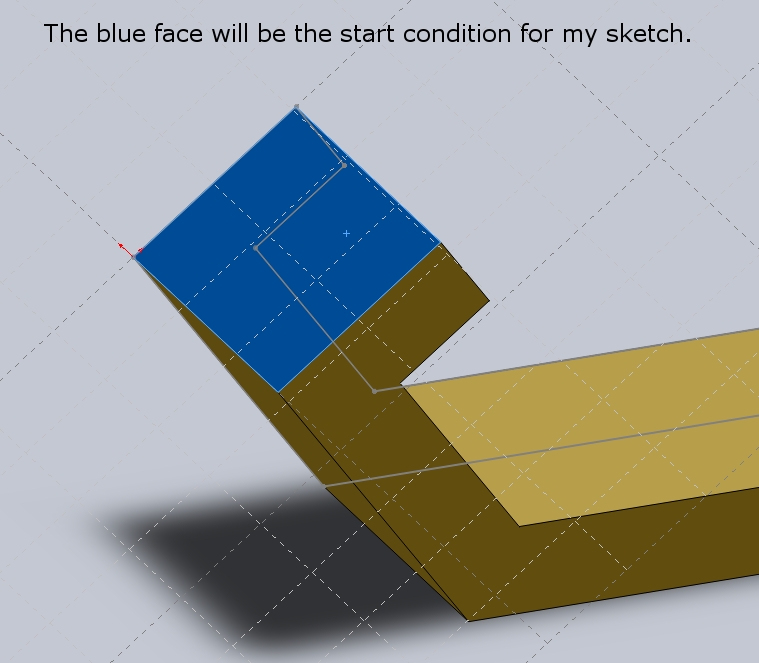
Parent child relations are time dependent in the feature tree (ie. order matters). Identifying which features are truly child features will help determine what start condition should be selected. This face is clearly a parent child as it clearly always is meant to create a single block with all edges tangent to others.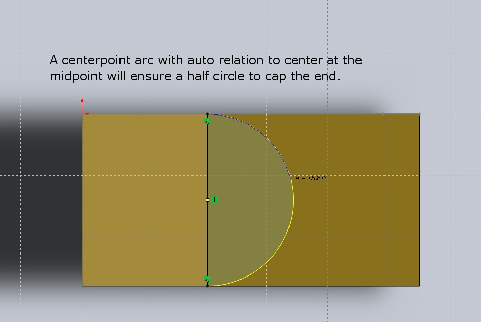
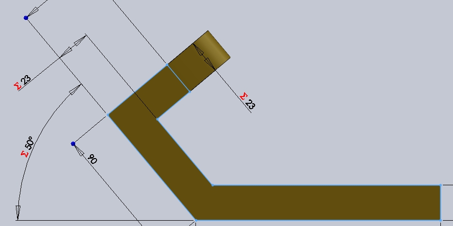
The sketch is then created. I used the auto relation to the midpoint to ensure that the half circle would always rebuild regardless of the thickness of B (my initial extrude). 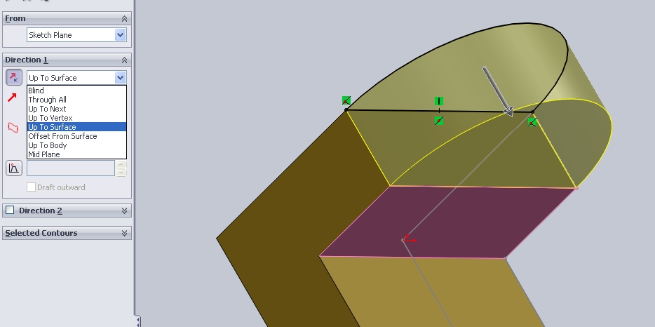 For the end condition I know that I only want the part to be of thickness D, as shown in the sample test. I could use a blind extude and link the dimension to D but that just leaves one more equation I have to worry about. However I know that the bottom face is always going to be “D” distance due to parent sketch (pictured below). Because of this it’s easier to simply use the “up to face” end condition. It is also good to note that the selected surface is viewed by the software as extending indefinitely so even of a feature extends outside of the modeled and shown portion of a surface the extension of the surface will be used to cut.
The basic end condtions are:
Blind- Very basic will go through any modled componetns for a given distance.
Through All – Will extend up to and thru all existing bodies
Up to Next – Will extend only up to the next surface
Up to Vertex – Will extend up to a given vertex. The vertex does not have to be in the line of the extrude of cut. Up to will be measure perpendicular using an extrude direction.
Up to Surface – Great for relating to existing geomety
Offset from Surface – Useful for clearances this is used in many part designs to create uniform wall thicknesses and allow for tolerance clearance.
Up to body – For multi body parts or in asemblies. Good for components that are to be modeled with zero clearance. Care should be taken when using this in manufacturing as it applies to tolerances.
Midplane – Uses the sketch as the center line of a mirror. Good for modeling but dimensioning these can lead to confusion as the overall thickness will be doulbe any input value.
Hi. This is a useful blog for those who are preparing for the exam. I would just like to ask if you got the exact value of the mass for question no.2 of this sample test.. Thanks in advance.
Hi, i found the error on my model. It was the top hole which was linked to the thickness of the model. I thought there was some error on it. Thanks anyway.. Have a nice day.