
After establishing the basic functions of sheet metal modeling (flanges) it’s time to start putting some more detail into our models. The first place to look is going to be the “Corner” features. When the sheet metal toolbar is present this icon actually represents 3 options:
Closed Corner: Saying this feature is “more detailed” is misleading. Rather it’s an easy and intuitive way to complete a design while avoiding some hassle. A corner could conceviably be closed using a series of Linear edge flanges, tabs, etc. all with odd profiles. Rather than waste time creating this though SW does the legwork for you. This feature works similar to the “Extend Trim” popular in sketches. Fairly straightforward, just select the features you want to form a corner, select the corner type, and let SW go to work. The only variable here is the gap distance which is typically driven by the type of welding that will be used (or rather the quality of the welder be it human or machine). Consult a sheet metal supplier for the best options.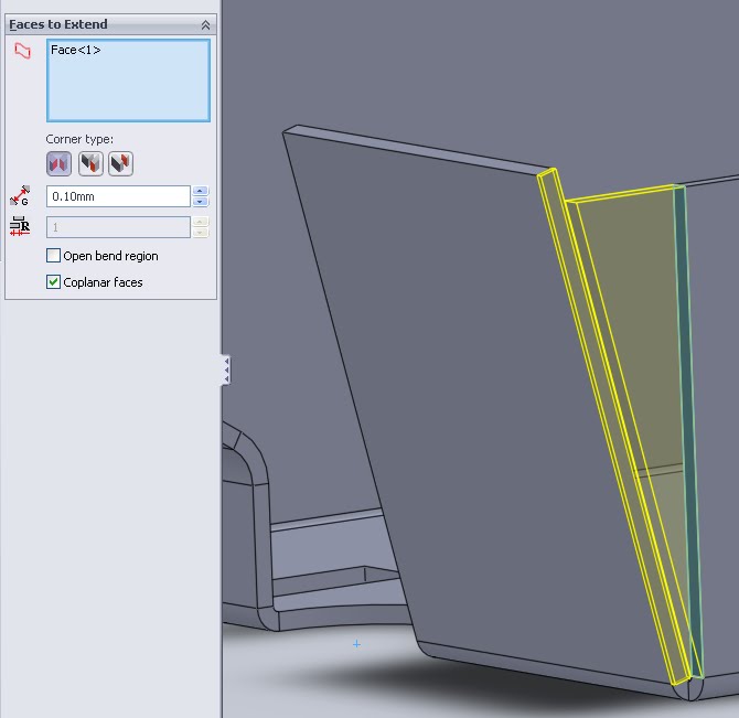
Welded Corner:
The welded corner feature is as much cosmetic as it is functional. Not only does it add a nice looking weld bead to seal a corner (if “add texture” is checked), it also easily denotes a weld feature on a print.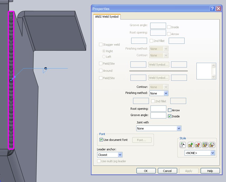 The best list of weld symbols I could find freely available helps to properly denote these items in conjunction with GD&T, although a google image search turns up some good results as well. Some of these change but in general that guide works but for applications where precise notation is important an actual copy of the standards is helpful as well.
Break-Corner/Corner-Trim:
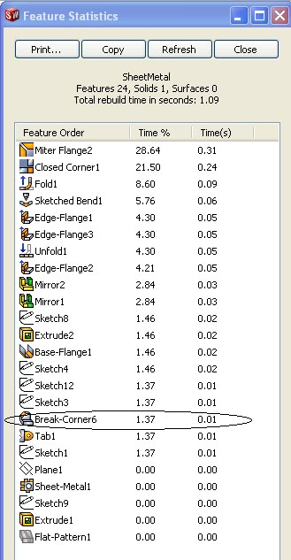
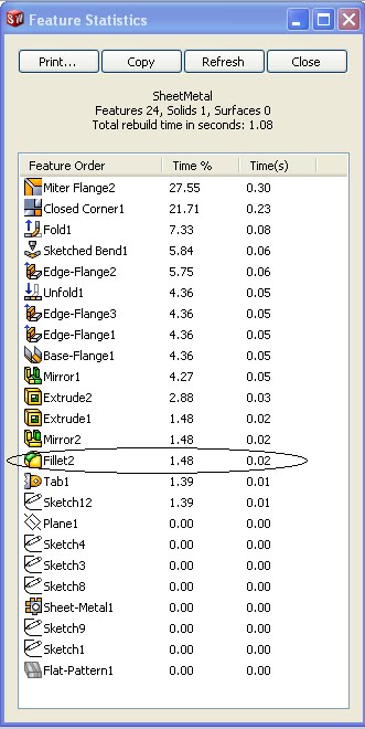
This one is very basic and is essentially another way of making a Fillet or Chamfer. In a series of quick testing the sheet metal option (Break Corner) was preforming slightly better than a Fillet Chamfer. This makes sense due to the extra options allowed in the Fillet Feature. Break corner the software will only select edges that are of the material thickness, or perpendicular to the flat sheet metal. These corners are then filleted prior to any bends, as they would be when a manufacturer creates their flat profile. Other edges that may be filleted are more difficult to create in manufacture, genreally requiring grinding or a more sophisticated profile cutting (stamping). Here is seems Solidworks understands what corners are mostly changed and has built a custom property just for those making things easier on a desinger who is unfamilar with the manufacturing process.
A must say a very comprehensive analysis !
Good job indeed !