
To start creating a weldment a path for each member must be present. This means a sketch must be created to represent the members paths. For simple boxes and very basic weldment parts sketches can be laid out in a traditional 2d fashion, but to really control things it is typically easier to create a 3d sketch. With the ability to locate a point anywhere in space, sketching in 3d is sometimes difficult. There are some tricks to help simplify the process.
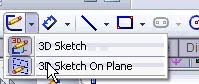
First to start a 3D sketch select it from the drop down below sketches (seen below) or Insert>3dSketch. Note that because the 3dsketch is a drop down, if you use the toolbar to exit sketches it will take an extra mouse click to get out of a 3dsketch. Instead to when it comes time to exit the sketch
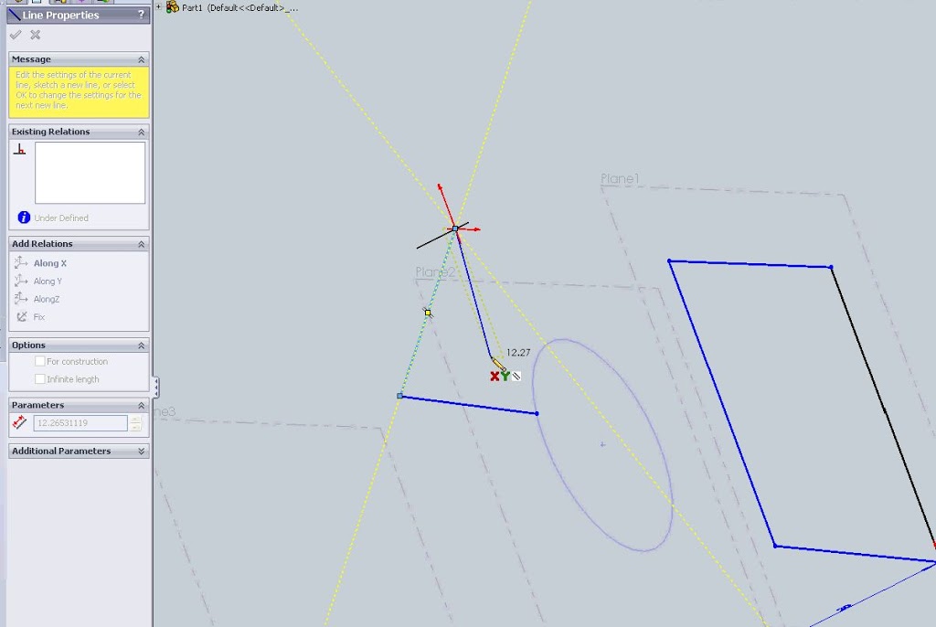
All the same sketch tools will apply for 3dsketching, but how to constrain the points of each entity is key. Initially a triad will appear with two red axis and one black axis. The two red axis are the plane on which you will be sketching. Hit the Tab key and the plane will change.
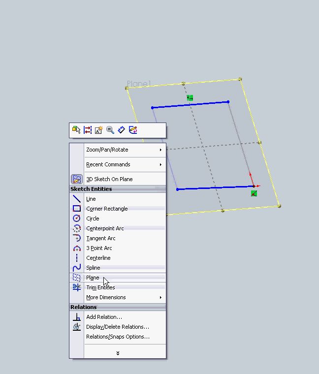
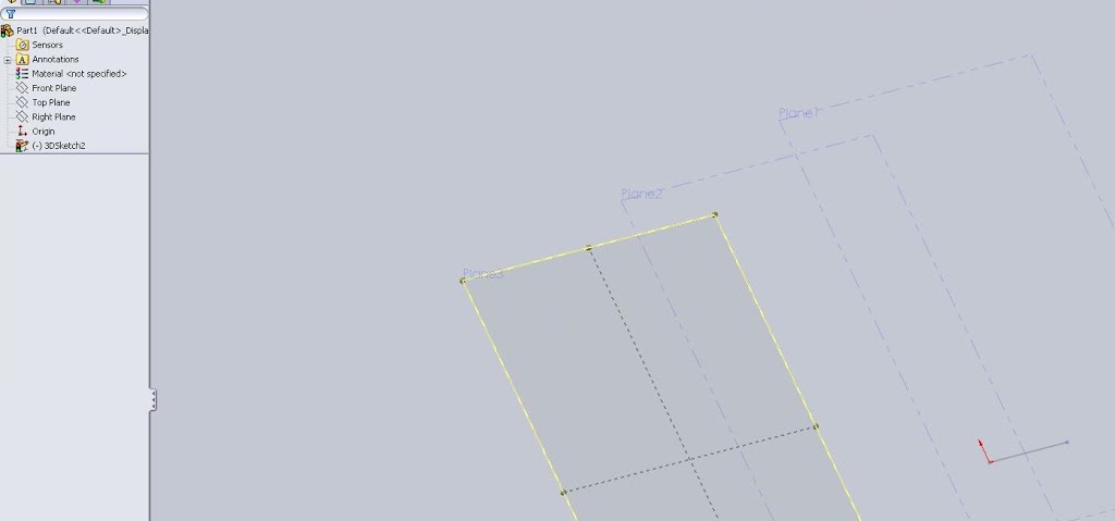
This allows a rough sketch to be created at first, but even with the two red axis highlighted it is possible to put a point on another plane. When doing so a box will be drawn with yellow build lines. This is only for visual purposes and shows a user where the cursor is in 3d space. All of this becomes a bit confusing, and there are times when even in a 3d sketch it is important to say on the same plane. 3dSketch planes help accomplish this. Similar to reference planes, 3d sketch planes can be inserted for referencing purposes. Right mouse button click while in a 3d sketch and select the “Plane” option (image below).
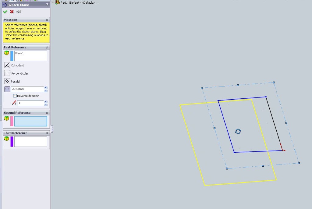
After selecting this option a feature manager will appear allowing for the creation of a 3dsketch plane (image above). This is NOT a reference plane. 3dsketch planes are contained within a 3d sketch and will not appear as a feature in the feature tree. In the image below three 3dSketch planes have been added but it is clear in the feature tree that only one feature is present, the 3dsketch
You can sketch on the 3dsketch plane by selecting that option from the original sketch drop down icon (3d Sketch on Plane) and then selecting the plane. Once this has occurred the sketch tools will lock onto that plane until another action is taken, no more 3 dimensional dashed yellow build lines.
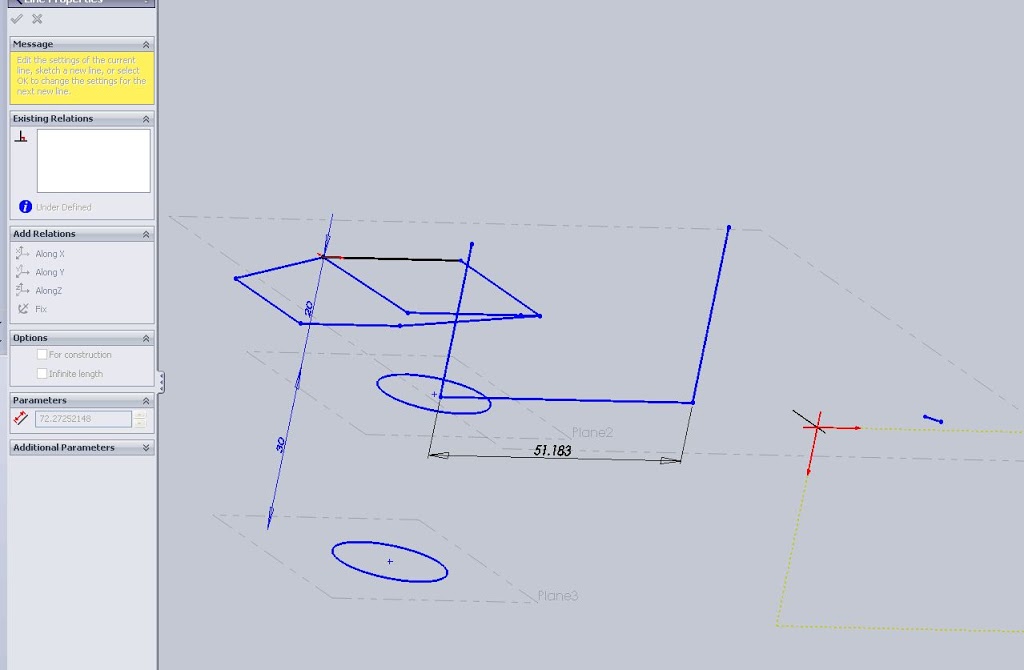
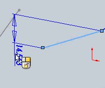
Dimensinoing is also imporatant for 3d sketches. Nothing is different about dimensioning, the smart dimension tool still works like a charm.

The one thing that may be difficult when dimensioning is figuring out what exactly is being dimensioned. Because an entity is in 3d space it is conceivable that it could be dimensioned in all three as well as a length dimension that spans all three. If a dimension is selected and not placed moving the cursor around may toggle these option. For tight spaces the placement of the dimension may be difficult so lock in which plane the dimension references by clicking the right mouse button.
Another handy option when creating 3d sketches is the ability to put a point on a plane. Ctrl select a point and plane (it can even be a 3d sketch plane) and the add relation option will include an “On Plane” option. This reference does exactly what is expected.

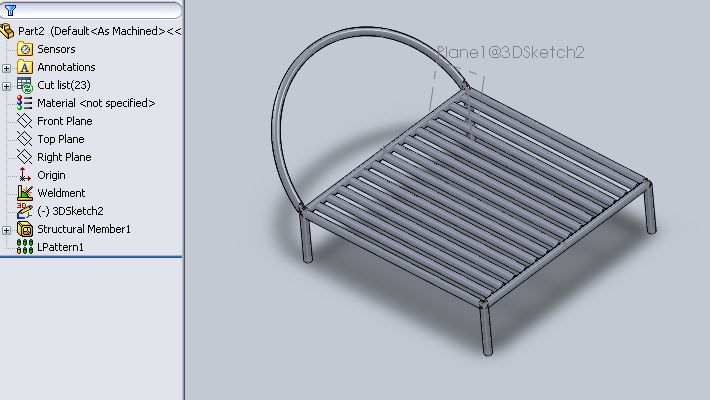
Using all of the above will help to create a clean, fully dimensioned 3d sketch that. With so much power it is possible to create a massively complex weldment structure with only a few features.
3d Sketches are just one of the suggested study topics for the CSWP Weldment exam. To review for other portions of the CSWP Weldment check out the main post.